Introduction: Pulley-Powered, Robotic Swing Arm Lamp


You will need:
Tools:
-Wire Cutters
-Hacksaw
-Ratchet or wrench
-Power Drill
-Laser cutter (optional)
-Hot Glue Gun
Electronics:
-2x hobby servo motors
-Arduino/RaspberryPi/Elegoo kit
-Breadboard
-Joystick Module or 2 Potentiometers
Supplies/Other Materials:
-Lamp from junk shop
-Lamp Base (mine is an old one I had from Ikea but usually they come with the lamp)
-Hose Clamps
-Cord (experiment with various tensions and cord types)
-sewing machine bobbins
-x2 Nylon cabinet rollers
-Cable Organizers (optional)
-Various other hardware
Step 1: Repairing Junk Shop Lamp


As with all my projects, one of my priorities was to not purchase and new supplies, and instead rely on recycled or up-cycled components. The price to pay for trying to offset your carbon footprint is, of course, convenience. The articulated lamp I purchased at a local junk shop was quite beat up, so It had to be repaired. First, I had to snip the lamps cord in order to pull it out of the broken beam for fixing. With a hacksaw, I removed the mangled end of one of the lamp's beams (pictured). After removing about an inch of busted beam, I then had to remove an inch from the parallel beam to even it out. To finish it off, I eyeballed new screw-holes with my power drill on both beams and re-assembled.
Step 2: Installing Servos


For this, I used two right angle brackets with affixed hose clamps to hold the motors in for easy removal. Mark and drill the holes for the right-angle brackets along the base somewhere, aligned with the axis of rotation—which in this case is horizontal to the Lamp's base, and vertical to the Lamp's central shaft. This part is somewhat easy, just be careful and make sure to unfasten the hose clamps before attempting to drill through them as they can be pretty hard to drill through. When the assembly of the brackets and clamps is done, just roughly bend the clamp into a rectangular shape and fasten around each servo and tighten.
After this, I made up some laser cut discs of various sizes to try using as winches to drive the pulleys. After some experiment and swapping out of wheels, the ones I decided to were 2.5" in diameter for the lamps's shaft/X-axis and two additional 2.5"+ 1" diameter discs for the base assembly.
Step 3: Installing the Pulleys


Once the Servos are in Place, it was time to start making this robot move! I decided on pulleys rather than gears mostly because I have no experience working with gears and did not feel like designing and fabricating my own gearbox for this one purpose. I also ended up liking the pulley system because the lamp's movements seemed more natural, and almost reminiscent of an early Automata.
Step 4: Circuitry & Code

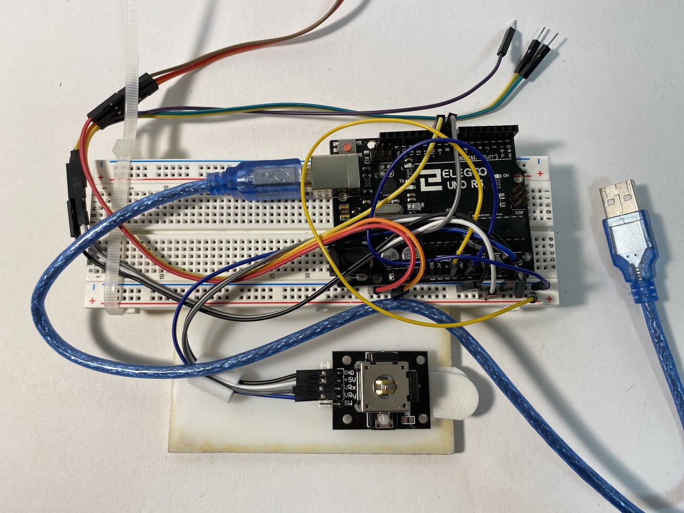
First, I prototyped the circuitry for controlling both of my servos with TinkerCad Circuits. Here is the final schematic I settled on, which can be easily reconfigured to use either two potentiometers as input, or a joystick. The code is a simple program which also works with the circuit reconfigured for joystick input. Here is the paste-bin for the finalized code: Here.
Step 5: Conclusion & Next Iteration Notes


In the end, my fully-assembled robotic lamp was functional, however; the servo motors were not powerful enough to consistently move the lamp. The movement was very jerky and sporadic, which I liked, but often it did not move at all. The hobby-grade servo motors I used made a horrible twitching noise when in "idol" position. This could potentially be prevented in two ways:
1. Using stepper motors to wind the pulley cords and stop at desired positions rather than using servos to assume certain angle values on demand.
2. Adjusting my code to have an idol state in which the servos are not receiving any input when it less than a certain value. Because of the way I mapped different input angle values to the servo motors, they are constantly in a state of being powered or receiving some minute input signal, even when nobody is touching the controller.
I would also like to make a better remote controller. I would swap out the joystick—which is very finicky—back to two potentiometers. An IR transmitter/receiver for wireless functionality would be a fun addition as well. Of course, my prototype controller is only mounted to a piece of acrylic with velcro, so I would definitely make as dedicated housing for my wireless controller.
In conclusion, I had a lot of fun with this project, and would love to see anyone else's take on a pulley-powered robotic lamp!


