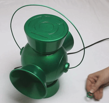
Introduction: Qi Green Lantern Charger
I wanted to have a Green Lantern Power Battery for quite some time. Sadly the original DC Collectibles ones are ridiculously expensive. After a bit of research I decided to build my own. Instead of just copying their functionality I decided to make it actually useable as a cell phone charger.
You can simply place your phone onto it and it will be loaded. The only requirement is that your phone can be charged with Qi (please check out Wikipedia should you want to learn more about Qi). But don’t worry if your phone doesn’t come with Qi, there are cheap adapters you can use (as you can see in the pictures I had to use one, too).
Another functionality that the Power Battery has is that you can turn on the light with a ring.

"In brightest day, in blackest night,
No evil shall escape my sight.
Let those who worship evil's might
Beware my power--Green Lantern's light!"
As you can see in the pictures, there are also three extra USB plugs in the back to charge more than one phone.
Please check out this link should you not know what power batteries are. Long story short, they are used to charge the Green Lantern Power Rings. By the way should you not like the green colour, there are many different versions.
Step 1: The Design
I designed everything in Fusion 360. Most of the design is quite simple and can be done by rotating and extruding sketches.
The only thing that I found tricky to do was to make the small indent that goes all around the middle part. Luckily Fusion 360 has an awesome feature helping you to do so.
Simply make a sketch in the middle, like the one shown in the first picture. Afterward close it and open a new sketch. Select "Project/Include" and then select "Intersection Curve". You will have to select one line/curve at a time, but as you can see it works really well.
Afterward you will have to open a new sketch and draw the structure you would like to subtract, as shown in the fifth picture. Make sure to select the right plane. Now all that is left to do is to select “CREATE”, “Sweep” and then the structure, as well as the path.
You can play around and download my design here:
Step 2: Top and Bottom
I decided to design the top as two parts, so that it can be printed without any support structures. Simply glue the logo plate to the top. Make sure to align them right.
I printed all the parts as a “fast print” on my Ultimaker, because I was impatient and I knew that after priming and sanding it would look smooth anyway.
Be careful when breaking away the support structures from the bottom part, since the walls between the USB plugs are rather small.
Step 3: Printing the Middle and Painting
Next print the middle part. I went through a few design iterations concerning the lenses and went with the ones I uploaded to this step.
Since I am a perfectionist I decided to give the Power Battery a smooth and glossy finish. I used three thin layer of primer and sanded everything. After another thin coat of primer I went with green paint and a glossy finish.
The lens is printed with PET filament, 100% infill and a high layer resolution.
I decided to add magnets to attach the top and the bottom, even though they are not needed since everything fit really well.
Put the lenses through the bottom or top hole and carefully push them in place.
Step 4: Electronics Part 1
I used this charger by AUKEY. To be quite honest the main reason for my decision to use it was that it has green USB plugs.
It turned out that it was difficult to take apart and I had to carefully use a chisel.
Afterwards I unsoldered the USB plugs and the power plug and soldered them back in place, as shown in the pictures. Don't forget to place the power plug cables through the hole in the bottom. I used a strong two component glue on the back of the parts, to hold everything in place
Step 5: Electronics Part 2
I used this Qi charger for the project. You can simply screw it apart and use some hot glue to hold it in place at the top. Use some tape to prevent the wires from getting in the way of the light.
As a light I used this cheap camp light bulb. It was also simple to take apart. I wanted the light of the Power Battery to be activated with a ring. Therefore I decided to add a reed switch. Simply connect it and glue it into the slot I designed.
Print the holder I attached to this step, glue the lamp circuit board to it and connect all the wires. As shown in the pictures.
Attachments
Step 6: The Ring
You can find my design of the ring here:
Please feel free to adapt it so that it fits your finger. Simply glue a 8x2 mm magnet into it, prime and paint it.
Step 7: Handle
It took me a while to get the handle right. At first I tried bending a piece of wire, but it looked horrible (also the paint didn't stick to the aluminum wire I got).
So I went to my local hardware store and picked up a cheap ($2) hand net for kids and was quite happy with the result. Simply print the two small adapter pieces, bend the ends of the wire and attach them.
Spray paint the handle and push it into the holes of the power battery.
Congratulations you are done.


