Introduction: RF Probe
Probe for measuring in the Radio Frequency range built inside an earphone jack, designed to have minimum capacitance and complete shielding.
Step 1: The Parts
A diode. Germanium point contact, OA79 or 1N34 is the preferred and traditional choice. But a modern substitute will be a schottky (gold bonded) diode. These have a low forward voltage, below 250 millivolts or so, versus the 600 or so of the silicon diode.
A few capacitors, chip type, value not critical, around 1 nf to 100 nf. (or 1000 pf to 0.1 microfarad)
One resistor, 1 Megohm.
One stereo earphone jack.
One pin from a turned pin IC socket. This forms the 'hot' end of the probe, so that various pins can be inserted for probing. A short piece from a needle for exploratory work. A piece of wire soldered to the circuit board when using it for a tuning up session, requiring it to be in place for a long time.
The circuit is traditional, as below:
C1 R<--||-------/\/\/\/\-------------o + | | --- | ^ | /-\ diode === C2 | | | |<--------------------------------o -
Step 2: Connect It Up
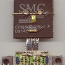
I used a small sliver of circuit board to hold C1. The turned pin socket was fitted to one end, the capacitor C1 soldered to it and then the resistor and diode leads formed to shape and soldered to the capacitor. It is shown next to the stereo earphone jack in order to see whether it will fit. Adjust sizes, get a smaller capacitor etc until it does.
The socket, capacitor and supporting board will go inside the barrel of the jack.
Step 3: Take the Jack Apart
A bit of filing, twisting and pulling will result in the jack coming to pieces. It is composed of a large number of precision formed metal and plastic pieces.
We need just the outer shell and the cover - It is best that the cover of the jack is metal, otherwise the shielding will not be perfect.
Step 4: Form the Body
The body of the probe is made from an old ball point pen. A piece of brass tube was found to serve as a join between the shell of the stereo jack and the ball pen body. The rubber grip from another pen was then slid over the metal to insulate it from accidental contact with circuit parts.
A molded mono earphone lead was used to get the signal out from the probe.
Step 5: Put It All Together
I used teflon tape to insulate the turned pin socket and capacitor, which had to go inside the barrel of the jack. A dab of petroleum jelly kept its bore from filling up as superglue was applied to hold it in position.
A HAM friend of mine measured about 5pf of capacitance for this probe, which is pretty good.
In use, a sharp probe is inserted into the turned pin socket. The ground lead is wire wrapped around the barrel of the jack. This is necessary if accurate measurements are to be made in a noisy environment.
I hope this will be of use to the HAMs among us.


