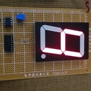
Introduction: RGB Electronic Die
This project is an RGB Electronic Die that generates the codes from 1 to 6 through 7 RGB LEDs as outputs for showing the mentioned numbers while the inputs are the codes generated by a 7490 counter fixed to count from 000-101. For carring out the RGB Electronic Die, it's necessary to design a decoder interface between counter and display by being this last one: a configuration of 7 RGB LEDs referenced previously. Also, we'll need to use a rotary switch of 4 poles y 3 positions for selecting the three possible colors: Red, Green or Blue.
Step 1: Bill of Materials
1 PCB 9cmX 15cm
7 5mm RGB LEDs
7 LED Mounting Hardware LowPro T1-3/4 Clear
1 IC7490
1 IC7408
1 IC7432
1 IC7404
1 IC555
4 Socket IC 14-Pin Dual Wipe Low Profile 0.3 Inch Wide
1 8-Pin IC Socket Dual Wipe Low Profile 0.30 Inch Wide
1 Potentiometer of 10K
1 Resistor of 470 Ohm, 1/4Watt
1 Electrolytic Capacitor of 1uF
1 Voltage Regulator 7805
1 Switch Push Button Tactile
1 Rotary Switch 4 poles y 3 positions
1 9V Battery Snap with 6 Inch 26 AWG Wires
1 9V Battery
Some connecting wires
Step 2: Schematic I: the Design
Schematic I is the design of your project.
Step 3: Schematic II: the Project
Schematic II is the whole project.
Step 4: Schematic III: Clock Circuit
Schematic III represents the clock circuit that you need in your project.
Step 5: Identifying RGB LEDs
Before installing the RGB LEDs, you need to Identify correctly the pins of all RGB LEDs that you are going to use in your project.
Step 6: Install the LEDs and IC Sockets
Once installed the LEDs and the IC sockets, you can connect the LED's cathodes each other.
Step 7: LED's Cathodes to IC Sockets
Note that you will be connecting the LED's cathodes to IC7490 in its pins 7 & 10 while IC7408 and IC7432 in theirs pins 7.
Step 8: Install the Capacitor
Install the capacitor of 1uF by connecting it to pin 1 of IC555 its negative polarity while its positive polarity to the pins 4 & 8 of that same integrated circuit. Besides that, connect from pin 1 of IC555 to pin 7 of IC7404 and to LED's cathodes.
Step 9: Installing the Pot & Resistor
Install the pot of 10K and resistor of 470 Ohm by following the instructions on your schematics.
Step 10: Install the 7805
Install the voltage regulator so that you can do all interconnections among the integrated circuits and 7805. That is, the pins that will be connected to +5V: pin 14 for IC7404,IC7408 & IC7432, pin 5 for IC7490 and pin 4 & 8 for IC555.
Step 11: Install the Switch & the Battery Snap
Install the switch and the battery snap with wires red & black so that you can do the connections at the rest of circuit.
Step 12: Make Hole of 3/8"
Need to make a hole of 3/8" so that you can install the rotary switch.
Step 13: Identifying the Rotary Switch
Identify the pins of your rotary switch by identifying each pole from 1 until 4 and begin with the first position in Red for each pole. That is, pole 1: Red, Green, Blue, pole 2: Red, Green, Blue, pole 3: Red, Green, Blue, pole 4: Red, Green, Blue. Check your schematic.
Step 14: Install the Rotary Switch
Install the rotary switch and the plastic knob and do all connections carefully. Note that you can fold each pin of the first position for establishing a color; for example, you can begin with red to connect all red colors from the pole 1 to pole 4 according to the schematic cited.
Step 15: Connect the 9V Battery
Connecting the 9V battery, you can play with your RGB Electronic Die and you also have the option of selecting from three colors: red, green or blue. Enjoy it.


