Raspberry Pi Shutdown Button

129K22531

Intro: Raspberry Pi Shutdown Button

As everyone at some point will recognise the Raspberry Pi doesn' t include any kind of shutdown button. So the only way to power it off is by unplugging it from the power supply. To make sure you get no corruption of your data files on the SD card you should shutdown the Raspberry before powering it off. So the whole procedure can be a bit annyoing especially if you want to use the Raspberry as some kind of embedded PC e.g. a media server or an internet radio.

The Raspberry Pi Shutdown Button provides a small circuit that includes the features:

  • sending a shutdown signal to the Raspberry if the Shutdown Button is pressed
  • waiting for the Raspberry to shut down
  • Powering off the Raspberry after save shutdown
  • Powering on the Raspberry after the Button is pressed again
  • LED light indicating the current state: On / Shutdown / Off

STEP 1: Parts

You need the following parts:

  • Atmel AVRtiny with 8 Pins (attiny13 / attiny85)
  • Pushbutton
  • 2 BC337 transistors
  • 1 relay
  • 1 electrolytic capacitor 680µF
  • 1 green LED
  • 4 pin connectors
  • a veroboard
  • some kind of AVR ISP programmer (I used AVR ISP MKii)
  • resistors

STEP 2: Schematic

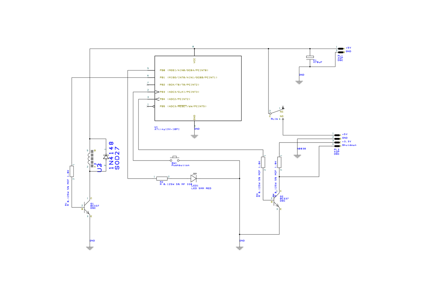
This is the Designspark Schematic I used for the Raspberry Shutdown Button. The AVR is connected to a relay that switches the supply voltage of the Raspberry Pi. A led indicates that the Raspberry is switched on. In shutdown mode it will start blinking. There is also a shutdown signal that tells the Raspberry to halt before the power is cut off.

STEP 3: AVR Programming

Here is the short listing of the AVR program.

STEP 4: Raspberry Pi Shutdown Script

The Raspberry Pi needs a script that tells it to shutdown if it gets the shutdown signal. So the next thing we' ll do is write a Python script that waits for this signal on a specified GPIO pin. Here we' ll watch out for GPIO pin 7. On the model B this is GPIO4. Save this short script in something like /home/pi/pishutdown/pishutdown.py.

pishutdown.py

#!/usr/bin/python

# Import the modules to send commands to the system and access GPIO pins
import RPi.GPIO as gpio
import os

#Set pin numbering to board numbering
gpio.setmode(gpio.BOARD)

#Set up pin 7 as an input
gpio.setup(7, gpio.IN) 

# Set up an interrupt to look for pressed button
gpio.wait_for_edge(7, gpio.FALLING) 

# Shutdown
os.system('shutdown now -h')

Next we need a shell script that starts our Python script with root access. Put the shell script in the same directory as our Python script.

pishutdown.sh

#!/bin/sh
cd / cd home/pi/pishutdown sudo python pishutdown.py cd /

Add a logging directory by typing:

mkdir /home/pi/pishutdown/logs

Use crontab to autostart the script. Open the crontab editor by typing sudo crontab -e in the Console. Append the following line:

@reboot sh /home/pi/pishutdown/pishutdown.sh >/home/pi/pishutdown/logs/cronlog 2>&1

Reboot...

STEP 5: Put Everything Together

Now connect the Raspberry Pi and the Shutdown board via the GPIO pins. Add supply voltage to the shutdown board and after booting properly press the Shutdown button for about a second. Now the led should start blinking and the Raspberry should begin the halt sequence. After a while the supply voltage for the Pi will be switched of by the relay. To switch it back on just hold the Button for about a second.

30 Comments

I planned to do something like this but I was going to use a second GPIO to create a watchdog signal like a pulse so the IVR can tell if the Pi is running. This way the power can be removed when the OS actually shuts down and could also be used to reboot a crashed pi.

How can I upload the hex file to the attiny?I tried avrdude but it doesn't seem to work? Has anyone rewritten the program in arduino IDE instead of cpp?

Couldn't you just shut down via the terminal?

Yes you can. But sometimes you don' t have one. E.g. when using as mediabox.

Hello!

please upload a binary hex file.

I just uploaded a hex file for attiny85 at 1MHz. I also provided a Makefile for compiling and uploading.

Sencs!

makefile dont downloadable as a php in this engine.

The content of the Makefile is:

--------------------------------------------------

F_CPU = 1000000

MCU = attiny85

PORT = /dev/cu.SLAB_USBtoUART

PROGRAMMER = stk500v2

all: main.hex

main.hex: main.elf

avr-objcopy -j .text -j .data -O ihex main.elf main.hex

main.elf: main.o

avr-g++ main.o -o main.elf

main.o: main.cpp

avr-g++ -g -mmcu=$(MCU) -DF_CPU=$(F_CPU) -O3 -c main.cpp -o main.o

upload: main.elf

avrdude -P$(PORT) -c$(PROGRAMMER) -p$(MCU) -U flash:w:main.hex

clean:

rm main.o main.elf

very thanx guys great work
So, I'm assuming you're using a DC SSR? Any particular brand, or just look for as many amps as possible? I got a few stereos and even a Krueg just begging to be dismantled.
I actually don' t use a SSR for this. Just a simple print relais. I wanted a small size so I used a Maluska FRS1B-S, 24V-, 1A. That is actually enough as the Raspberry only takes a maximum of 500mA. But an SSR is definetly an option too. Greetings
This is AWESOME! I've been wanting to do something like this for a while and since I'm building an HTPC with my Pi2 model, this should be an excellent mod.

Hi, first ty for this code, but i have one question. I noticed since i put this code at startup in my rasp pie model 1 b that it runs much slower then before. Can it be due to loop that is taking up too much processor power?

You are right. The while loop draws a lot of processor power. It is better to use the wait_for_edge() function of the gpio package. So the whole script becomes even smaller:

#!/usr/bin/python # Import the modules to send commands to the system and access GPIO pins import RPi.GPIO as gpio import os #Set pin numbering to board numbering gpio.setmode(gpio.BCM) #Set up pin 17 as an input gpio.setup(17, gpio.IN) # Set up an interrupt to look for pressed button gpio.wait_for_edge(17, gpio.FALLING) # Shutdown os.system('shutdown now -h')

I' ve already been using this modified script a while but missed to update this Instructable. I will modify the original version asap. Thanks for the Feedback.

If I am not concerned about actually removing power from the board, but I want to send a shutdown signal when a power button is pressed over the GPIO pins, do I even need the circuit? It seems (in my very limited knowledge) that the Python script monitoring the GPIO pins could start the shutdown script and then I could pull the power manually.

This particular unit that I am working on is going to be used in Kiosk mode to display a certain web page. Basically a digital sign. There will be no interface available to the user (though I have SSH control through another machine). I want to make it easy for them to flip a switch and shut this down. Power can be cycled if it needs to be booted again.

Thanks for any input as to whether I can just run your Pythoun script (or a modified form) that senses when to start the shutdown/halt command when the switch is applied.

If you just want to send a shutdown signal to the Raspberry you don' t need the circuit. You can just use a pullup resistor to +3.3V and a switch to GND. As you said the Python script will initiate the shutdown and then you can pull the power.

Thank you! I had figured that was true based on some more stuff I read later today. I plan to build the switch this weekend. I will try to report back what I learned.

Everything works exactly as I wanted. Thank you! I have prototyped everything and will wait until I get my screen in this week to see how that affects my connectivity to the GPIO pins.

Great. So maybe I' ll find you later on Instructables with your project :)

More Comments