Introduction: Relays (DC): 99.9% Less Power & Latching Option
Relay switching is a fundamental element of electrical control systems. Dating back to at least 1833, early electromagnetic relays were developed for telegraphy systems. Prior to the invention of vacuum tubes, and later semiconductors, relays were used as amplifiers. That is, when converting low power signals into higher power signals, or when remote load switching was beneficial or necessary, relays were the state-of-the-art option. Telegraph stations were linked by miles of copper wire. Electrical resistance in those conductors limited the distance the signal could be communicated. Relays allowed the signal to be amplified or "repeated" along the way. This is because wherever a relay was connected, another power source could be injected, boosting the signal enough to send it further down the line.
Electromagnetic relay switching may no longer be state-of-the-art technology, however, it is still widely used in industrial control, and where true galvanic isolated switching is desired or required. Solid-state relays, the second of the two primary categories of relay switch, have some advantages over electromagnetic relays. SSR's can be more compact, more power efficient, cycled faster, and they have no moving parts.
The purpose of this article, is to show a simple method to increase the power efficiency, and functionality, of standard DC actuated electromagnetic relay switches.
Step 1: The 3 Common Electromagnetic Relay Types
1. Standard Non-Latching (monostable):
- Single coil of magnet wire surrounding a core of low magnetic permeability (only magnetized when coil is energized).
- Switch armature held in it's stable state (not pulled in) by a spring.
- Requires a DC voltage to be applied to the coil, in either polarity, to pull in the switch armature.
- Requires a continuous current to temporarily magnetize the pole piece on the armature and hold this state.
- More current is required to pull the armature in than is required to hold it in.
Uses: General purpose.
2. Latching (bistable):
Single Coil Type:
- Single coil of magnet wire surrounding a semi-magnetically permeable core (remains lightly magnetized).
- Switch armature held in unlatched state (not pulled in) by a spring.
- Requires only a short pulse of DC power to be applied to the coil, in one polarity, to pull in and magnetically latch the switch armature in this state.
- Requires only a short reverse polarity pulse to be applied to the coil to unlatch.
Dual Coil Type:
- Two coils of magnet wire surrounding a semi-magnetically permeable core (remains lightly magnetized).
- Switch armature held in unlatched state (not pulled in) by a spring.
- Requires only a short pulse of DC power to be applied to one coil, in one polarity, to pull in and magnetically latch the switch armature in this state
- Requires only a short pulse of DC power to be applied to the second coil, in one polarity, to unlatch.
Uses: Outside of industrial control, mostly used for RF and audio signal switching.
3. Reed Type:
- Single coil of magnet wire surrounding a core of low magnetic permeability (only magnetized when coil is energized).
- Closely spaced spring metal contacts hermetically sealed in a glass tube (reed).
- Reed is positioned close to the coil.
- Contacts are held in the stable state by their spring tension.
- Requires a DC voltage to be applied to the coil, in either polarity, to pull the contacts opened or closed.
- Requires a continuous current to magnetically hold the contacts in the non-stable state.
Uses: Almost exclusively used for small signal switching.
Step 2: Pros & Cons of the 3 Types
1. Standard Non-Latching (monostable):
Pros:
- Usually the most readily available.
- Almost always the lowest priced option.
- Versatile and reliable.
- No driver circuitry required.
Cons:
- Not power efficient when conventionally driven.
- Produce heat when energized for long duration's.
- Noisy when switching.
2. Latching (bistable):
Pros:
- Power efficient, sometimes more so than SSR's.
- Once actuated, hold either state even when no power is present.
Cons:
- Less readily available than standard relays.
- Almost always priced higher than standard relays.
- Usually fewer switch configuration options compared to standard relays.
- Require driver circuitry.
3. Reed:
Pros:
- Usually the most compact of the 3 types.
Cons:
- More specialized, less available, fewer options.
Step 3: Squeeze That Juice Like a Miser
A conventional way to reduce the holding current of a standard relay, is to connect the coil through a series resistor with a large value electrolytic capacitor paralleled with the resistor. Most non-latching relays only need about 2/3 (or less) of the actuation current to hold state.

When power is applied, a surge of current sufficient to actuate the relay, flows through the coil as the capacitor charges.

Once the capacitor is charged, a holding current is limited by and supplied through the paralleled resistor.

Step 4: Maximize Your Miserly Mischief
With a carefully placed neodymium magnet and a little circuitry, the holding current of a DC relay can be reduced by greater than 99.9%. This technique will work with many... mini relays, but not all.
Before Proceeding:
- Soldering skills and basic electronics knowledge are needed to complete this project.
- Circuit supply voltage range is 5VDC to 24VDC.
Due to voltage drops and reactances in the circuit, choose a relay with a coil voltage rating approximately 25% lower than the supply of your circuit. For example, with a 12V supply: 12V - 25% = 9V.
Parts:
- 1 - Non-Latching Relay: 3VDC - 12VDC
- Neodymium Magnets: 15mm x 2mm - 10mm x 20mm x 2mm
- 2 - NPN Transistors: Q1 & Q2 2N3904
- 1 - Schottky Diode: D1 1N5817
- 1 - R1 2MΩ 1/4W Resistor
- 1 - C1 1000μf 16V - 35V Electrolytic Capacitor
Tools:
- Soldering Iron & Solder
- Multi-Meter
- Hot Glue & Gun
The housing of the relay shown was cut open for demonstration purposes, but shouldn't be necessary in practice. In most cases, placing the magnet directly above the switch armature on the top of the plastic housing as shown will work. It may be necessary to try magnets of different size and strength. As well as trying thin plastic or cardboard shims underneath the magnet, to space it further away from the armature.

Magnet Placement:
- Place the magnet as shown in Figure 1.
- Connect one multi-meter probe to the common switch terminal. Connect the other probe to the normally open switch terminal. Set the multi-meter to the maximum ohms scale, or continuity test mode.
- Apply power to the coil (in either polarity).
- If the meter shows all zeros, or the buzzer sounds, remove power from the relay coil.
- If the meter continues to indicate the switch is holding closed, secure the magnet in this position with tape or hot glue.
- If not, reverse polarity to the coil. If the switch closes, remove power, if it holds, secure the magnet in place.
- If the relay doesn't latch in either polarity, try adjusting the magnet position, or placing a thin non-magnetic shim underneath the magnet.
- Continue to repeat these steps until the switch actuates, and remains latched when power is removed. Then fix the magnet in place.
- Mark the power supply polarity that works on the relay body.
- Reverse polarity to the coil again and confirm that the relay unlatches. If not, further adjustment may be required.
Adding the magnet in this way, causes the relay to function as a latching relay. The following circuit, allows the relay to behave like a standard non-latching relay, but with over a 99.9% reduction in holding current.
Building the Circuit:
Solder the components together as shown in the sequence of photos at the top of this section. Be sure to match the circuit polarity to the polarity previously marked on the relay body. If the orientation is inverted to whats shown in the photos, the magnet can be flipped over.
Circuit Functionality:

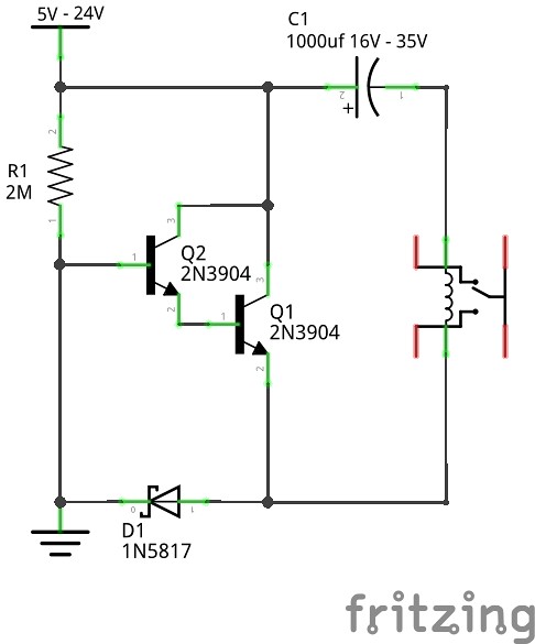
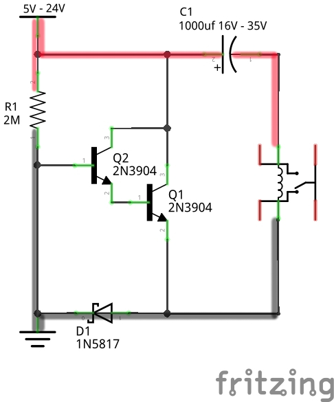
When power is applied, the relay coil is briefly energized as capacitor C1 charges. Simultaneously, the base of Q2 is reverse biased because it is tied to the supply ground. This holds Q2 and Q1 OFF, and also allows supply current to pass through R1.

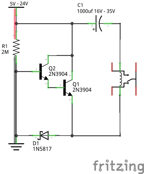
After C1 charges, virtually no current flows through the relay coil, accept for a tiny capacitor leakage current, typically dropping to less than 1μA. The relay holds state because the neodymium magnet has latched it. As long as the circuit is connected to the supply, the base of Q2 is held reverse biased by the current passing through R1. This is how to calculate that current: If the supply is 12V, then 12/2,000,000Ω (R1 2MΩ) = .000006 A or 6μA.

When the supply is disconnected, the base of Q2 is forward biased through R1 by the charge stored in capacitor C1. This turns ON Q2 and Q1, allowing the charge stored in C1 to be rapidly discharged through the relay coil reverse polarity, which unlatches it. D1 prevents Q2 from becoming reverse biased by the discharging of C1.

Step 5: Latching Option
With a few additional components, the circuit can be configured to allow selecting between non-latching and latching modes.
Additional Components:
- 1 - NPN Transistor: Q3 2N3904
- 1 - PNP Transistor: Q4 2N3906
- 2 - R2 R3 4.7KΩ 1/4W Resistors
- 2 - S1 S2 SPDT Switches
Q4 is the latching switch, and Q3 is the unlatching switch. The B connection only needs to be pulsed to ground momentarily for the relay to latch. The A connection only needs to be pulsed to the supply positive momentarily for the relay to unlatch. When S1 and S2 are closed, the circuit is in non-latching mode. When S1 and S2 are open the circuit is in latching mode. In latching mode, a micro-controller on a shared supply can be used to control this circuit, by providing the momentary pulses to the A and B connections.

Second Prize in the
Electronics Tips & Tricks Challenge


