Introduction: Remote Sensing of the Water Tank Level and LoRa Transmission for Remote Pump Control
I have to fill a tank 1.5 km away, so I create a 2-part controller.A server with a relay to manage the pump and a client solar/battery-powered to check the tank’s status and notify the server’s status.
I develop a PCB client and server and the relative software.
Step 1: Problem
First the problem: I must refill a 1,5Km far water tank, so I need two devices:
- a server that manages a pump: if the remote tank isn’t full the server start the pump with a relay and when the tank is full, stop the pump.
- Start-stop pump;
- Manage the remote message;
- Prevent dangerous action if the remote device is no more active;
- Monitor to select an operation mode and status.
- A client that is in a remote position (tank position) checks the water level and warns the Server if It’s all ok or the tank is full.
- Check the max and min level;
- Warn Server about status;
- Battery and solar-powered;
- Sleep mode if no more need.
Step 2: Microcontroller and LoRa Communication
Microcontroller
As usual, I’m going to use a WeMos D1 mini because is small and powerful, and I’d like to use WiFi (in the next release) to manage the configuration, more information on this tutorial. “ESP8266 tutorial (WeMos D1)“.
You can find the WeMos D1 on AliExpress WeMos D1 mini - AliExpress NodeMCU V2 V2.1 V3 - AliExpress esp01
Communication
For communication, I’m going to use 2 Ebyte e32 devices; check the devices in this tutorial, “LoRa e32 devices“.
You can find the LoRa devices here (433MHz 3Km) - (433MHz 8Km) - (868MHz 3Km) - (868MHz 8Km) - (915MHz 3Km) - (915MHz 8Km)
Step 3: Display
I love i2c devices, and in this project, I’m going to use an SDD1306, more information in this tutorial “OLED SDD1306“.
You can find here I2C SPI SSD1306 0.91 0.96 inch OLED
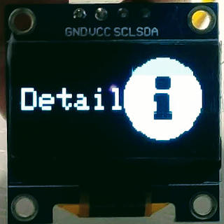
Remote water tank level pump controller display State detail ENG
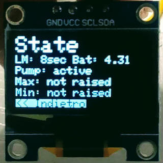
Remote water tank level pump controller display Interface status debug ENG
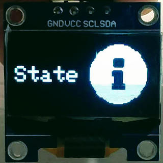
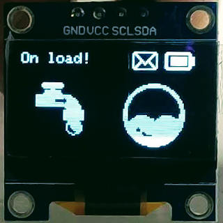
Remote water tank level pump controller displays State ENG
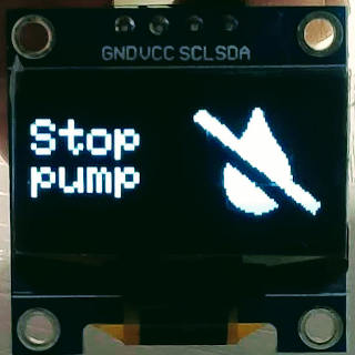
Remote water tank level pump controller display Stop pump ENG
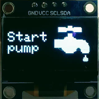
Remote water tank level pump controller display Start pump ENG
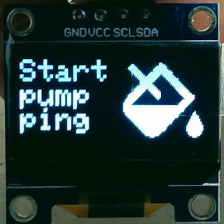
Remote water tank level pump controller display Start pump ping ENG
Step 4: Start Prototyping
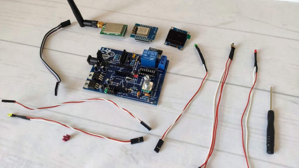
To start prototyping, I use a series of shields created for this use, the result seems quite unstable, but It works very well.
WeMos All Shield pcf8574 ssd1036 relay e32 Lora
All this shield is distributed for free, and you can buy the PCB from the PCB producer, the complete PCB of the Server, and the client. It’s also available.
For the Server I use:
LoRa wireless remote water tank and pump controller esp8266 Server PCB
For the client

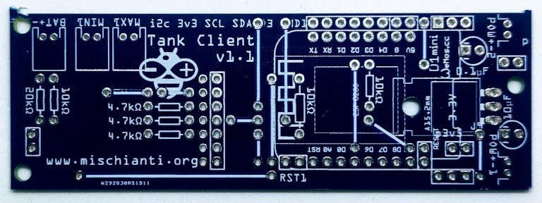
LoRa wireless remote water tank and pump controller esp8266 Client PCB
Step 5: Server PCB
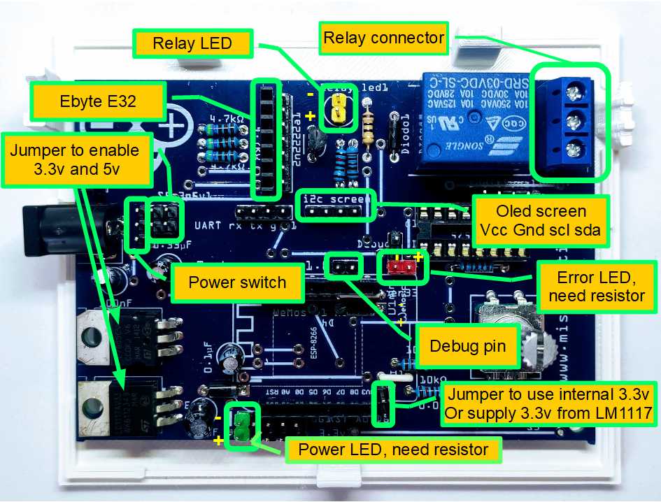
LoRa wireless remote water tank and pump controller (esp8266) Server PCB explained.
Then, we must start to assemble the components, the LEDs, switch, display, WeMos D1, and EByte E32.
LoRa wireless remote water tank and pump controller esp8266 Server PCB
You can find the software here and the PCB and the instructions here.
Step 6: Client PCB
For the client, I use the external module to manage the power supply, so there is no dependency for the people that don’t need to be autonomous with the battery.
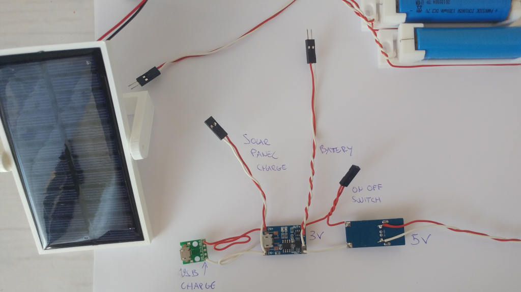
Battery and Solar panel circuit
You can find all the components of solar battery recharge on “Emergency power bank homemade“.
LoRa wireless remote water tank and pump controller (esp8266) Client solar battery charge
Assembly
For assembly, you can refer to the silkscreen of the PCB, and I do It quite verbose.
LoRa wireless remote water tank and pump controller (esp8266) Client PCB up
Then, we must start to assemble the component, the LEDs, switch, display, WeMos D1, and EByte E32.
LoRa wireless remote water tank and pump controller esp8266 Client PCB
You can find the software here and the PCB and the instructions here.
Step 7: Case for Server and Client
Step 8: Conclusion
And finally the assembled project.

Second Prize in the
Remote Control Contest


