Introduction: Robotic Arm Trifecta (Science Olympiad)


Welcome 2016 Science Olympiad Teams! The Robot Arm event is back and are you ready to make some kick-butt robots? Please leave a comment below rather that messaging us so that the community can grow as a whole. We loved this event and are happy to share what we learned for this year's competition!
In In the fall of 2012, we set out to construct a robotic arm for the Science Olympiad competition that would be capable of performing the required set of tasks efficiently and to perfection. This instructable will attempt to guide you through the thought processes used in the design and construction of this project. We spent countless hours working on this robot and hope to refine this into a condensed version for you to read at your leisure. We hope this can be an inspirational guide to help you through your next project.
Step 1: Get to Know the Masterminds

Before we begin, we'd like to
recognize all of the people and businesses that made this creation possible through their donations of time, resources, and guidance.
Although these companies were major contributors to the project, all of the design and the majority of the manufacturing were done by Jordan Vanderham and Matthew Budde, members of the West Ottawa Science Olympiad Team.
We would like to thank the following companies for being a part of our team and enabling us to make this robot:
Tric Tool, Lightning Machine, Spark Fun, Inovateus Solar, Metalution, Dimension Engineering, US Digital, Lakeshore Cutting Solutions, Trossen Robotics, and World Class Prototypes.
Step 2: Background


Special events in Science Olympiad typically run for two years and then cycle to a new category. In fall of 2011, the Robotic Arm event was announced and our thoughts went wild. Working through this drive, we designed and built a robotic arm which, while impressive at the time, had multiple problems and wasn't the best that we could do. This was a learning experience for the team; and one that we all benefited from greatly.
These pictures illustrate our first design. The arm used a hybrid drive of electric and pneumatic power to accomplish each task. We loved using the pneumatics due to their power and low cost, however, our approach raised some concerns, mainly about having a large tank of pressurized air strapped to a high school kid's chest. The next year, the event rules made this approach very difficult, so we abandoned that in favor of our new design. If you would like to learn more about our 2011 robotic arm, feel free to ask in the comments and we will deliver.
Attachments

Step 3: The Design Process (Thought)


As in every project, the design
stage can make or break the entire project. Before even picking up a pencil or drawing in CAD, we had to understand our problem. After reading the rules, we sat down with as many people as we could and started brainstorming. It is amazing what a group of people can do with ideas bouncing around constantly changing through each person’s point of view. We found ourselves spending much more time than anticipated just ironing out small design details during this process. Due to all of this attention, though, the rest of the project went remarkably smooth.
The Design:
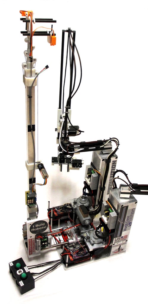
We spent time researching proven robot arm designs on the internet. At first, we considered making a "traditional" articulated joint style robotic arm, but we found that to be unfeasible due to the size restrictions, cost and high motor holding torque. After discarding that concept, we came across the SCARA style design. This struck us as being more efficient and easier to implement and control. This design allowed us to use lower torque motors due to this designs more planar nature, so the motors would not have to directly support the weight of the arm. Implementing the control would also be easier as the positioning of the effector of the arm did not require the movement of every motor.
The Claw:
The claw went through two manufactured design iterations with multiple concepts for each. The first design used a motor and a threaded rod to move one side of the claw towards the other. There was a torque clutch that activated a switch to stop the movement of the claw when it grasped an object. This method was proven, but it did not have the grip strength that was necessary for some of the heavier items. It was also rather noisy and not an elegant solution.
The second design used a Dynamixel AX-12A servo to pull one side of the claw towards the other along four guiding rods using the turning motion of the servo to wind a cord onto a spool from either side. This was a very effective method due to being able to control the torque of the servos to prevent catastrophic ping-pong ball crushing. The linear motion of this claw made it easier to pick up objects since one side of the claw never moved, allowing us to use that side as a reference point and the other side as the gripping force. The other advantage to this claw design is that, unlike some other designs, it moves in a linear fashion. Other claws, such as the scissor type claw, plunge as they grip. That extra motion would complicate our elegant solution to object manipulation.
The Arm:
You can see the amount of design time that we put into this part by just looking at it. We were burdened with budget and size restrictions and tasked with range, strength, and ability problems. This arm was designed to play with our restrictions and optimize our strengths.
Attachments
Step 4: The Design Process (Computer Aided Design)


Click on the claw it is a GIF!
This robotic arm was designed in Autodesk Inventor to ensure that every part of the robot had a place and that all collisions were avoided. Collapsing three expensive robotic arms into a 30 cm x 30 cm x 100 cm box can be stressful, but after seeing it done in CAD, we knew it could be done in real life. CAD helped us visualize and collaborate on the same level. Having the robot drawn up in cad let us go directly to a 3D printer or a CNC machine for fabrication. Coming into a project like this, we knew that it has to be designed in a CAD environment, but this is not always the case. Some projects are faster to prototype without a 3D rendering but long term projects usually are assisted with CAD.
The usefulness of CAD was demonstrated when we were designing the claw (see animated picture). The drive servo had a rotation of 300 degrees and we optimized the pulley radius to the desired grasping width and strength.
Step 5: Materials
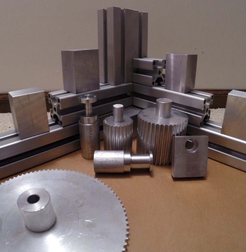


The main construction materials
for this robotic arm were Aluminum (cast and extruded) due to its high strength, low cost, and ease of machining. Aluminum provided a strong base and main support tower for the main rotational axis and each preceding joint. Carbon fiber (plate and square/circular tubing) was a key material in the construction and performance of our robotic arm. Due to its high strength to weight ratio we used it to connect each joint together to minimize momentum and strain on the motors as the arm swung around.
The carbon fiber was purchased from HobbyKing
Step 6: Machining


Being able to turn a raw chunk
of metal into a finished, precise, custom part is a wonderful thing to know how to do. The process is almost magical and it's so fulfilling to see your hard work and careful measurements turn out a small part that will ultimately be an integral part of a much larger machine.
We were fortunate enough to be granted access to multiple vertical mills for us to do the majority of our machining on. Prior to this project, we had limited machining experience between the two of us. By the time we got all of our parts machined, we were feeling pretty darn confident in our abilities to create precise, custom components. The only custom metal parts that were not machined by us were the brackets to hold the carbon fiber links. These were machined by the great people at Metalution, and they worked perfectly.
For the plate carbon fiber pieces, we used a small CNC cutter that our school had in one of the manufacturing technology classrooms. Machining this carbon fiber plate took quite a toll on the cutting tool and some of the edges were a bit fuzzy and frayed, so there was some cleanup work necessary after pulling them out of the machine. We weren't completely surprised by that, so we were prepared with 250 grit in hand.
Step 7: Printing


3D printing was a very
important part of this creation. Designing with 3D printing in mind enables us to not have to worry about the restrictions of subtractive manufacturing and just focus on optimizing the design. 3D printing also allowed us to prototype our claw design through its multiple reiterations and optimizations. Without this technology we would still be standing in front of a mill hashing out generation 1.298 claw. This technology is helpful, but it does not come without a few problems.
3D printing technology that was used to print our parts is similar to Full Spectrum's SLA 3D printer but with a flip. We received help for this project from a local prototyping company, World Class Prototypes, that had a 3D printer where a resin was deposited onto a build platform through thousands of tiny piezo electric jets. This layer was then cured with an ultraviolet light. This printer could deposit two types of materials, typically a hard structure resin, and a soft support material. This support material had to be power washed off, so our restrictions for this printer was the size of an object that we could hold while cleaning it up and learning the printer and its tolerances.
Step 8: Electronics
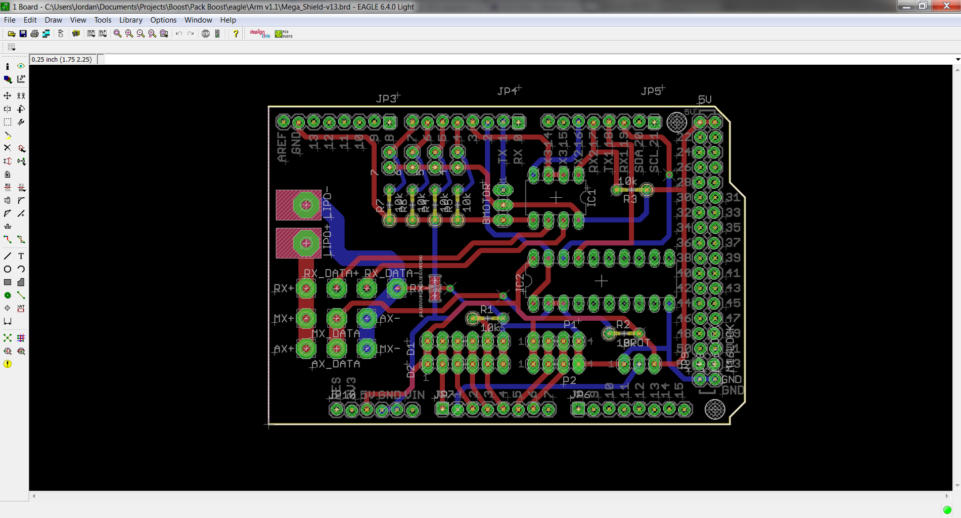

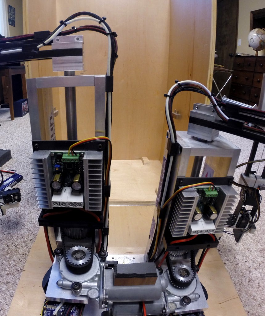
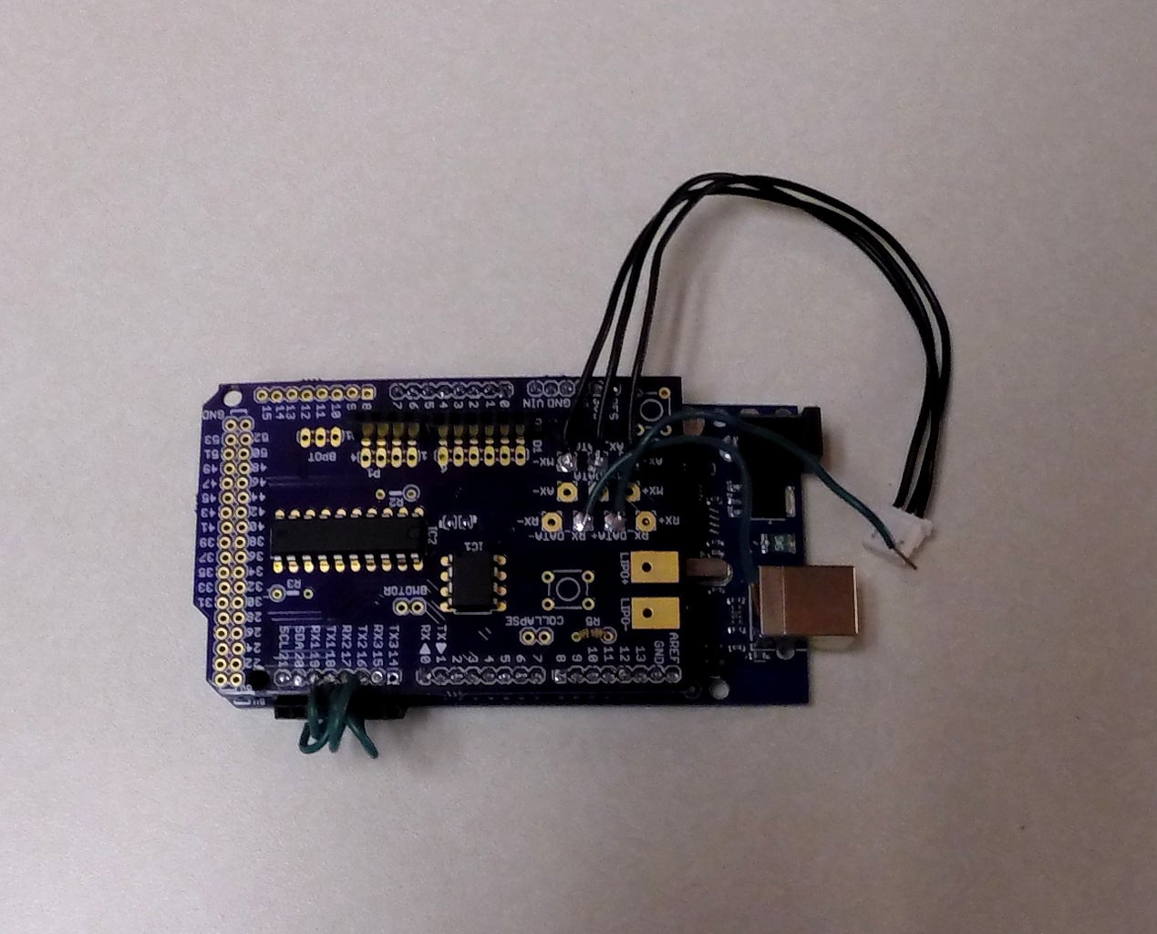
The two main arms are controlled by a pair of Arduino Mega Pro boards from Sparkfun. Although we didn't use near the amount of digital pins that these Mega boards offer, we chose them due to their multiple serial ports. Three serial ports were needed; one for each communications protocol to the different Dynamixel servos (will go further into depth about that in Programming) and one to the Syren motor drivers from Dimension Engineering.
We designed a custom PCB and circuit in EagleCAD to connect all of the necessary components to the Arduino. These include two buffer chips for communication between the Arduino and the Dynamixel servos, assorted resistors, and connections for power and communications between all of the components. These designs were then sent off to OSH Park for high-quality manufacturing.
The third extension arm is controlled by an Arduino Uno with a proto-shield on top to connect the controls to the necessary inputs and outputs of the microcontroller.
The controllers for all three arms plug into their respective boards through rows of header pins for ease of connection. The PCBs are soldered to the Mega Pro boards to ensure reliable connectivity.
All three arms are powered by the same 11.1 volt lithium-ion battery from HobbyKing. Link
Components and Supplier:
Battery- https://www.hobbyking.com/hobbyking/store/uh_viewI...
Microcontroller- https://www.sparkfun.com/products/1100
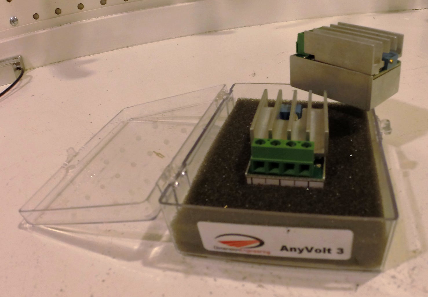
We also used the AnyVolt 3 for power optimization on our elbow servo, but unfourtionally we had to remmove them. Read more on step 12: Optomization.
Step 9: Motors and Drive


There are 16 motors used in
this design. 10 of them are Dynamixel servos (2 AX-12W, 4 AX-12A, 2 RX-24F, and 2 MX-64), 3 are car window motors, 2 are HobbyKing micro hobby servos, and 1 Maxon motor.
Each of the two main arms has half of the Dynamixel servos and one of the car window motors. The rest of the motors are used in the extender arm assembly.
We got our motor drivers from the great people over at Dimension Engineering. We used a Syren 50 for each of the car window motors at the base of each of the main arms and a Syren 25 for the car window motor that rotates the extender arm up and down. These drivers were a breeze to work with thanks to the Arduino libraries that Dimension Engineering supplies. (Seriously, we can't say enough about how helpful Dimension Engineering was throughout this project.)
Using a DC motor for the main base rotation drive was done because of the torque needed to control the base axis of the entire moving robotic arm. A standard servo motor would have cost an absurd amount and we thought we would take on the challenge of making our own. The difference between a windshield motor and a servo is just a bit of logic, and a high quality motor driver. With the motor drivers from Dimension Engineering in hand, we attached a photometer to the base axis and implemented a PD control loop as seen in the programming step. To achieve an even greater strength and control we implemented a 2:1 belt driven gear ration.
Step 10: Programming

This robot is powered by three different Arduino microcontroller boards. The two Arduino Mega Pro boards are both running the same program (more or less) while the third has a very simple program just to control the tilt and raising of the extension arm.
We chose to use three boards so that, in the event of a glitch in one bit of code on one arm, the other arms would be able to still function properly and still score points for the competition.
The main feature of the code was the PD control for the base motor. This allows the arm to move to its location without any abrupt stops when it gets there. The Syren motor drivers were extremely easy to send commands to, thanks to the libraries from Dimension Engineering.
The Dynamixel servos have a built in PID control, so all that needed to be done was to send the position commands to those. Because we used servos from the AX, MX, and RX lines, we needed two different buffer chips. We learned how to use the Arduino to control these servos from Savage Electronics and we use slightly modified versions of his libraries (included in the code folder). All that was done to modify these libraries for our use was to change the serial port in one library so that each buffer chip would have its own serial port.
When we started writing the code, we wrote each function step by step. We started by only running the code for the base motor, then we went on to add the pieces one by one further down the arm. We wanted to make sure that every piece of the code worked correctly before we tried every function together to reduce the risk of ruining all of our hard work up to that point.
The code folder here includes all of the libraries necessary for the code to compile and the Arduino sketches for each arm.
Attachments
Step 11: Troubleshooting


With hundreds of parts coming together there was bound to be at least one problem.
With every project there will be problems, but with every problem you get closer to completion. Going through this stage can be frustrating, but the way we found to deal with this is with a partner. We would keep each other sane in the early mornings and open each others eyes to the answer of a problem that was staring right at us. If you are working solo, sometimes the best thing to do is stand back and look at your current problem from a different point of view. Explaining your problem out-loud and dumbing it down can help you do just so.
Our biggest issues were with the linear slides and the backlash of the motors. Our custom PCB has a flipped trace which resulted in 8 hours of head banging and we never thought to think about wire routing while designing a robot that articulates at 17 points... oops.
Problems are meant to be over came so we did just that.
Step 12: Optimization


Sometimes the perfectly
optimized design that you have in your head has to make a compromise when it comes to reality. We always strive for perfection, but once in a while some ideas have to get put on the back burner for the next project. With this robotic arm we were restricted to use a battery that was 12 volts or less as according to the rules given to us at the beginning of the season. Working with our preferred battery type, Lithium-Ion, due to their high power density, we had a battery voltage of 11.1 volts nominal. In our situation we originally planned to use the AnyVolt 3 from Dimension Engineering to boost our battery voltage to 14.8 volts to better drive the elbow servos. The elbow servos were our biggest investment and we wanted to get the most out of them. A 3.7 volt increase may not sound like allot, but a 32 percent increase in torque would have given us an edge against the 3 minute competition time. After 2 months of building and design a rule clarification was released that disabled us from using any inverter that might adjust the voltage above 12 volts. This idea had to be scrapped in fear of being disqualified. These inverters pack a punch and are amazingly efficient in compassion to their size. We are using the AnyVolt3 to further our research in Dynamixel servos including the new Pro line.
Assembled and working, it was time to calibrate the PD control for the base motor. This would control the speed at which the arm would swing to a specified position and reduce the amount of backlash from the motor stopping suddenly. Since we didn't have any sort of way to easily adjust the values, we had to change the value in the code and re-upload every time we made the change. We started by turning up the P value first to a level that we were comfortable with. Then, we adjusted the D value until it moved nicely like we wanted it to. There wasn't much method to what we did, so we really just played around with the values until we liked it.
The claw grip strength was far too high in the beginning. On hard objects, it would try to over-torque itself and the servo would stop responding to preserve its life. To solve this, we just edited the max torque setting on the claw servo. Tada, problem solved.
Our extender arm was mainly limited by the amount of tubes that we could find to fit inside each other. That ended up being 7 tubes and it could reach about 18 feet up. The higher up it got, obviously, the less stable it was. At full extension, the top of the arm would sway around a couple feet back and forth and it would make it very hard for the judges to measure.
Step 13: Packaging


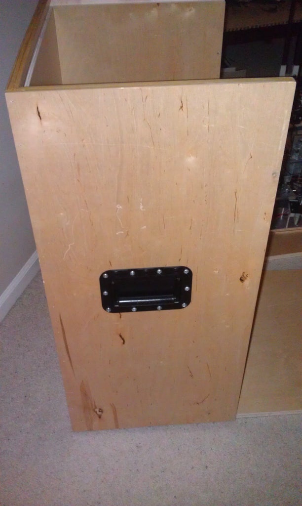
The case that we built ensured that the robot would be protected in its travels to all of the different competitions. A box was designed and cut out on the CNC table router at our high school and assembled. The robot slides in nicely in a folded up position and is held firmly in place with a combination of braces and padding in strategic locations. The case looked pretty spiffy to boot.
The two control arms were packaged individually in these cases from Harbor Freight. There were multiple layers of foam that prevented the arms from moving around while in transit.
Step 14: Conclusion


All of our hard work paid off
in the end! We placed first at both the regional and state levels of Science Olympiad and won first place in the regional and second place in the state levels of the MITES Competition.
Through this project, we learned a lot about engineering and how to go through the process of coming up with a thought and then turning that thought into a physical object that does exactly what it was intended to do. It was a very rewarding project and definitely the highlight of our senior year of high school. We came to realize that there are so many stages between prototyping and a device that you can trust and going through those stages just takes time.
These days, Jordan Vanderham is at Grand Valley State University studying mechanical and electrical engineering and Matthew Budde is at Michigan Technological University studying computer and electrical engineering. They are excited for the future to come and what project they are working on next,
Go out and do something that you never thought possible my friends! We just kept on pushing with the excitement of the journey and the love of engineering.

Third Prize in the
Full Spectrum Laser Contest

First Prize in the
Robot Contest

Participated in the
Arduino Contest


