

Introduction: SMART LAMP - Palmieri, Dobladez and Galván


Hi, we are Mateo Dobladez, Matías Palmieri and Thiago Galván, we are 14 years old, and we live in Campana, Buenos Aires. We study in the Tecnica Roberto Rocca school. The fact that we are going to learn a lot of things that are going to be useful in a future, motivates us.
This project is about the creation of a smart lamp (like the one in the photo) that has the possibility to change the intensity of the light provided by the natural light that it receives. Also, the lamp has servomotors with the ability to rotate the lamp in the same place and move an arm to light different places. The final product can be used like a nightstand or to light spaces that need more light in the dark.
We did a functional prototype of this exact same lamp and it worked just like this:
Above, you have a photo of what it should look like once finished and also it has a photo of how we managed to make it :
Supplies
Before to start you will need the link of the parametric model, in this you could see all the measures and dimensions of the lamp. For that, we used the program "Onshape", because is easy to understand and use:
You are going to need these elements:
Materials:
- 1 PVC tube of 500 milimeters of large and 40 mm of diameter
- 1 lampholder, can be something like the one above.
![]()
- You can select between wood, plastic or metal, but you must use a plate of approximately 700mm large, 150mm width and 5mm of thickness.
Electric components:
- 1 lightbulb ( 5 watts, 220 volts)
- 2 servomotors sg90
![]()
- 2 potentiometers
- 1 electric switch
- 1 relay. The model we used is this one:
![]()
- 1 photoresistor (LDR)
- 1 arduino UNO
- 1 protoboard
- x cant. jumper wires
- 1 cell phone charger:
![]()
Tools:
- Carpenter´s glue, a welder (can be any type) or liquid silicon (can be hot silicone aswell) depends on which material are you going to use of the mentioned before.
![]()
![]()
![]()
- 1 phillips screwdriver
- Drill (the wicks depend on the size of the different electronic components that you will use)
- 1 saw / bow saw
- Pliers (there are a lot of types, but you can use the one that makes you more comfortable)
- 1 Electronic welder, may be this one:
![]()
- Brushes to paint
Required assembly components:
- Welder tin:
![]()
- 4 Phillips screws
- Tape, can be paper tape or aislant tape, both works.
- Wicks for the drill.
- Acrylics, the color that you like the most to paint it.
(the amount of the components in which it is not specified, changes depending on how much you use)
Step 1: Construction


First, you have to cut the material that you selected in this measures:
- 150mm x 150mm square (x1).
- 150mm x 150mm square with an empty circle in the middle of 400mm of diameter (this is the cover) (x1)
- 150mm x 50mm rectangle (x4)
- 85mm x 50mm rectangle (x1)
- 65mm x 50mm rectangle with a square cut in the middle of it with every side measuring 25mm (x1)
Then, cut the PVC tube in two parts:
- One of 250mm large
- And the other of 170mm large
After that, you will have to build the base, for this part we recommend to use the assembly tools that we said earlier. Please watch the sketches with measures and copy it. In the sketch, you can see a rectangle in the middle of the base, but for that, the measures change depending the measures of the servomotors. If you use the same model as us, the measures of the part that holds the servomotor are:
- Rectangle of 18,5mm x 30mm and it have some walls that are 2,5mm tall covering all the exterior surface.
Then, you have to assemble the 250mm large PVC in the circle of the cover.
You don´t have to link the cover to its base yet.
Now, is time to build the "elbow", but for that, you must follow the measures from the sketch. You have to do 2 of those to then link them together to work as an elbow.
The final part is to glue the lampholder in the shorter PVC. Once you glue that, we can follow with the electronic part.
Step 2: Programming

After the shelling part of the lamp, you must continue with the programming of the electronic part of the smart lamp. For this, we used C++ programming languaje but you can use another one.
If you decide to use C++, you can use this exact same code:
#include <Servo.h>
Servo servo_A;
int grados_A;
Servo servo_B;
int grados_B;
int intensidad_led;
int Luz = 0;
void setup()
{
pinMode(3, OUTPUT);
pinMode(A0, INPUT);
pinMode(A1, INPUT);
pinMode(A2, INPUT);
pinMode(A5, INPUT);
Serial.begin(9600);
servo_A.attach(5);
servo_B.attach(6);
}
void loop()
{
digitalWrite(3 , HIGH);
Serial.println(analogRead(A0));
if (map(analogRead(A0),0,1023,0,180) != grados_A)
{
grados_A
= map(analogRead(A0),0,1023,0,180);
servo_A.write(grados_A);
}
if (map(analogRead(A1),0,1023,0,180) != grados_B)
{
grados_B = map(analogRead(A1),0,1023,0,180);
servo_B.write(grados_B);
}
if (map(analogRead(A2),0,1023,0,255) )
{
Luz = analogRead(A5);
if (Luz > 774) {
analogWrite(3, Luz);
} else {
digitalWrite(3, LOW);
}
delay(10); // Delay a little bit to improve simulation performance
}
}
This is too difficult to explain, but bassically, this is the correct code in text form, to achieve what we said in the introduction.
Now, you can go to the app "Arduino", copy and paste this code, check if the Arduino was correctly connected to the computer and then just click "upload".
Once you have done that, the code will be permanently (until you change it) uploaded to the arduino, so when you connect it to an external source of power, it should run this exact same code always.
Attachments

Step 3: Assembly of Electronic Part


For this step, you have to assemble all the electronic part of the smart lamp.
First, we recommend to use Tinkercad to simulate it. To make the assembly easier to you, we already do the simulation of the assembly and here is the link to view the simulation and how to connect all the electric components:
https://www.tinkercad.com/things/gHrWAVzxJoJ?sharecode=OKPpgTGqzjm_41VBTm_OdFkY2RgAvZPPw6bCqFrM3Tg
Also, you will have to make a rectangular hole in the longer PVC, the measures are 1,27mm x 2,3mm. It must be located like in the first photo (that is where the servomotor is going to be glued).
You must do a little circular hole in the shorter PVC to put the photoresistor, just like the second photo.
Now, you have to make some holes in the cover acording to the measures of the electronic components that you have. It should be like in the third photo.
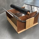
To connect the two PVCs, we are going to put these in the servomotor and ajust them with 2 screws:
![]()
If you have already saw the simulation, you can start the real assembly. First of all, you will have to connect each component in its port. Then you will have to connect them to GND and to 5v if neccesary but, as you might know, the Arduino only have one 5v and three GND ports and you will need more than that. So there is when the protoboard appears. You will have to assembly the protoboard inside of the base because it has interconnected pins where you can share the 5vs or the GND to more wires than the Arduino can provide. To connect every wire to each component, the best iw to weld them with tin and the electronic welder. This is going to ensure that the connections are better than usual and they don´t disconnect so easily.
Once you have done that, you must put every component in their appropiate compartiment, you can see that in the photo of above.
Please be careful with how you connect some components because you can burn it or in the worse case, it can explode and damage your skin, so please be careful with the polarity of the components and especially with the power source.
Another recomendation is to use long wires because it will a lot more easier. Although, not that long because there will be so much wires and it will be difficult to know which cable is which.
If you did all we mentioned, you can now safely link the cover to its base by using 2 screws.
Step 4: Enjoy
With all what we said, you will do a lamp just like ours in the photo! So now, the last step is just to enjoy with your brand new smart lamp and see if it works. If it doesn´t work, don´t get angry, just open the cover and look for a missing wire, a false contact maybe due to a bad welding, etc.
What do you think about it? Should we make a change on something?


