Introduction: Secure Communication Channel Encrypted With M9DES (My Modification of DES)
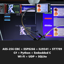
In this tutorial, I'll teach you how to build this handy device, how it works, and how to use it.
The security of this device is based on five pillars:
- MAC address is unknown to the attacker;
- Keys never transferred between the devices;
- IVs involved in the encryption/decryption process never transferred between the devices;
- The receiver only decodes messages after the IV adjustment;
- Brute-force attack is infeasible.
You can find the improved version here https://www.instructables.com/Doomsday-Messenger-W...
Supplies
- ESP8266 x2
- 16x2 LCD Displays x2
- I2C LCD Adapters x2
- Arduino Nano/Uno/Compatible board x1
- 470 ohm resistor x1
- PS/2 Keyboard x1
Step 1: Rijndael Substitution Boxes
Rijndael cipher (Advanced Encryption Standard) has two substitution boxes which are the inverses of each other. Rijndael S-Box takes 8-bit input and produces 8-bit output.
Step 2: DES
The Data Encryption Standard is a symmetric-key algorithm developed in the early 1970s. DES's main weakness is its key length. DES has a key with a length of 56 bits, which makes it vulnerable to a brute-force attack.
Step 3: 3DES
Triple-DES is an attempt to eliminate the main weakness of the DES by simply tripling it.
Step 4: M9DES
Modernized 9DES is my attempt to modernize the 3DES by adding Rijndael S-boxes and IVs to it.
Rijndael (AES) S-boxes are used to increase the entropy of the ciphertext, therefore making it more resistant to cryptanalysis.
The integration of the Initialization Vectors protects the cipher from replay attacks, and at the same time, prevents the attacker from learning about the content of the captured packets by implementing the chosen-plaintext attack.
IV5 is used to adjust the IVs on the receiver.
Transmitter sends the package with encrypted IV5 right after being turned on. The first package that the receiver takes must be the package with encrypted IV5, otherwise, the receiver will print "Incorrect IV!", turn the LCD's backlight off, and will not accept any messages until it will be rebooted and provided with the valid package.
Step 5: Download the Firmware
You can download the firmware here: https://github.com/Northstrix/M9DES_ESP8266
Step 6: Download and Install the Libraries
You can download the libraries here:
DES_Library: https://github.com/fcgdam/DES_Library
Software Serial: https://github.com/PaulStoffregen/SoftwareSerial
ESP Software Serial: https://github.com/plerup/espsoftwareserial
GyverBUS: https://github.com/AlexGyver/GyverLibs/releases/do...
LiquidCrystal_I2C: https://github.com/fdebrabander/Arduino-LiquidCrystal-I2C-library
You can unpack the content of the archive into the folder: ...\Arduino\libraries.
Or open the Arduino IDE, click to the Sketch -> Include Library -> Add .ZIP Library... and select every archive with libraries.
Step 7: Get the MAC Address of the Receiver Board
To get the MAC address of the board upload this code to the board.
#include <ESP8266WiFi.h>void setup(){ Serial.begin(115200); Serial.println(); Serial.println(WiFi.macAddress());}void loop(){}Then open the serial monitor, and reboot the board.
If done correctly, you should see the MAC address in the console.
The MAC address of this board is 5C:CF:7F:FD:85:1D
Step 8: Generate the IVs
There are lots of methods to generate a random number. I've decided to throw 20-sided dice to do this. Every time I was getting a number with two digits, I was writing down the last digit.
By the way, involving your pets in the IV generation process can add more randomness.
Eventually, I've generated these five 8-digit numbers:
83775105
36484135
91484639
31829232
64383785
The maximum value of IV is 99999999. If you've generated something more than 99000000, I would advise you to either change the first digit or generate the new IV.
Step 9: Upload the IVs Into Both ESPs
Open the sketch called IVs and replace the IVs in this sketch with the ones you've generated.
If you did everything right, you should see the IVs in the Serial Monitor.
Step 10: Generate the Keys
You can throw dice or use "dice throwing software" or hash the picture.
To make it easier, copy this array four times and replace Fs with your values.
Note that the key is in hexadecimal format.
byte key[] = { 0xFF, 0xFF, 0xFF, 0xFF, 0xFF, 0xFF, 0xFF, 0xFF, 0xFF, 0xFF, 0xFF, 0xFF, 0xFF, 0xFF, 0xFF, 0xFF, 0xFF, 0xFF, 0xFF, 0xFF, 0xFF, 0xFF, 0xFF, 0xFF, };Step 11: Modify the Firmware
Open the files ESP_transmitter.ino and ESP_receiver.ino
Replace the receiver's MAC address in the sketch ESP_transmitter.ino with your MAC address.
uint8_t broadcastAddress[] = {0x5C, 0xCF, 0x7F, 0xFD, 0x85, 0x1D};Replace the keys in the firmware with the ones you've generated.
Step 12: Flash the Transmitter Board
If the firmware doesn't compile extract the content of the GyverBus-main.zip into the folders Firmware_for_Arduino and ESP_transmitter.
Step 13: Flash the Receiver Board
Step 14: Flash the Arduino
Step 15: Build the Transmitter
You can find a Schematic diagram for the transmitter in step 16.
You can find a Circuit diagram for the transmitter in step 17.
Step 16: Schematic Diagram
Step 17: Circuit Diagram
Step 18: Build the Receiver
You can find a Schematic diagram for the receiver in step 19.
You can find a Circuit diagram for the receiver in step 20.
Step 19: Schematic Diagram
Step 20: Circuit Diagram
Step 21: Test the Device
Power up the receiver first, then power up the transmitter.
You should see the inscription "Delivery success" in the display connected to the receiver and the inscription "IVs adjusted!" in the display connected to the receiver. Type the message on the keyboard, press "Backspace" to remove the last character, press "Enter" to send the message.
The blue display is connected to the transmitter, and the yellow display is connected to the receiver.
Due to the poorly implemented PS/2 keyboard-to-ESP interface, I would recommend you to type no faster than one symbol per second.
Important note: The receiver only accepts the IV5 which is more than the stored IV5 but no more than the stored IV5 + 50. So, don't turn the transmitter on without the receiver more than 49 times in a row.
Step 22: Final Thoughts
That's all I can get from DES. I made it protected from the replay attack and ensured that the same message produces different output each time it encrypted. I also made it more secure and more resistant to cryptanalysis.
If you like this project, please share the link to this tutorial.
Thank you for reading this tutorial.

Participated in the
DIY Summer Camp Contest


