

Introduction: Serial Control of JTD-0801 HDMI Switch & Upscaler


The J-Tech Digital JTD-0801 HDMI Switch, Upscaler, & Audio Extractor is a nice piece of equipment for a media setup at a reasonable price.
The Switch has 3 HDMI, 1 VGA, 2 Component, & 2 AV Inputs with 1 HDMI output. The HDMI is passed through while the other inputs are upscaled to 1080p. Optical & Coaxial SPDIF audio out let it connect to a speaker system.
The switch can be operated by an external IR remote & receiver, but they are now always included or not always the best match for a specific setup. Thankfully this is easily fixed with an Arduino. This Instructable will cover how to control the JTD-0801 using an Arduino via an IR Blaster, optocoupler, or old fashioned button presses.
Supplies


- JTD-0801 HDMI Switch & Upscaler
- Arduino Board
- IR Blaster or Optocoupler
- Some connecting wire
- Solder Iron & Solder
- 3.5mm male plug(Optional)
- NPN Transistor & base Resistor (For Method 3)
- Arduino IDE with IRremote Library
The Switch/Upscaler website is:
https://jtechdigital.com/product/8x1-audio-extractor-1080p/
Any Arduino will work. A Micro, or Nano is recommended due to size/power consumption.
Either an IR Blaster & IR Receiver can be used or an Optocoupler. The IR Receiver should have came with the JTD-0801. If not the pinout is as follows:
Ring: Signal
Tip: 5 volt
Sleeve: Ground
CAUTION: The JTB-0801 Uses 3.3v logic. The Input button is 3.3v. The LED's use 5v through a separate chip. a 5v Arduino is used here as the Input button is switched through a NPN transistor and not exposed to 5v.
Note: The LED's logic is inverse. The Pin is always pulled High (5v) until activated when it is pulled LOW. Arduino is activated by a LOW signal.
Step 1: Figure How You Are Going to Connect the Arduino
There are three options for controlling the JTD-0801 with an Arduino. Pick the one you wish to follow:
Method 1: IR Blaster
- Easiest & least wiring. No need to open the JTD-0801.
- Requires Original or replacement IR Receiver & IR Blaster for Arduino.
- Arduino powered by external source.
Method 2: Optocoupler
- Requires Optocoupler & 3.5mm male jack(TRS)
- Can also be soldered internally if desired.
- Arduino powered by external source.
Method 3: Button Press
- Must disassemble the JTD-0801 & solder some wires to the board.
- Most complicated but easiest if do not wish to mess with IR codes.
- Arduino powered from internal source.
Method 1 & 2 are essentially the same as 2 just replaces the IR Blaster & Receiver with an Optocoupler. Method 3 is the most difficult but most DIY and versatile.
Arduino can either be powered externally or from the 5v present in the JTD-0801. Your choice. Just connect Arduino 5v pin to a 5v source on the JTD-0801 and GND to Ground.
Step 2: IR Blaster


- Connect the IR Receiver to the JTD-0801. Is a simple 3.5mm jack.
- Connect an IR blaster to your Arduino. You can either use a ready made module or a bare IR LED & resistor. Your choice. The blaster gets connected between Arduino Ground & Pin 3 via a resistor. @20 ohm is used here.
- Upload the attached Sketch JTDSerialControl.ino to the Arduino
- Place the IR Receiver & Blaster in a direct line of site of one another.
- Open the Arduino IDE Serial Monitor & enter the corresponding number to the input you wish to change to. Consult the chart below for inputs.
InputNumber Entered:
VGA 0
HDMI 1 1
HDMI 2 2
HDMI 3 3
AV 2 4
AV 1 5
Component 2 6
Component 1 7
Standby Mode s
Attachments

Step 3: Optocoupler


- Connect a 3.5mm male plug to the 3.5mm IR receiver jack on the JTD-0801.
- Connect the Sleeve pin of the 3.5mm male plug to the corresponding pin on the Optocoupler.
- Connect the Ring pin of the 3.5mm male plug to the corresponding pin on the Optocoupler.
- Connect corresponding pin(opposite of input) on optocoupler to Arduino GND
- Connect corresponding pin(opposite of input) on optocoupler to Arduino Pin #3
- Upload the attached Sketch JTDSerialControl.ino to the Arduino
- Open the Arduino IDE Serial Monitor & enter the corresponding number to the input you wish to change to. Consult the chart below for inputs.
InputNumber Entered:
VGA 0
HDMI 1 1
HDMI 2 2
HDMI 3 3
AV 2 4
AV 1 5
Component 2 6
Component 1 7
Standby Mode s
Attachments
Step 4: Button Press(Soldering to JTD-0801)


- Disassemble the JTD-0801. There is 4 phillips-head screws. The top cover will then pull off.
- Unscrew the main board from the bottom case.There are 6 more phillips-head screws.
- Located the singular pushbutton on the board. Is on top side to the right.
- Locate the pin located towards the back side closest to the input jacks(See image). This is where a wire will need to be soldered.
- Solder a wire to the pin from step 4.
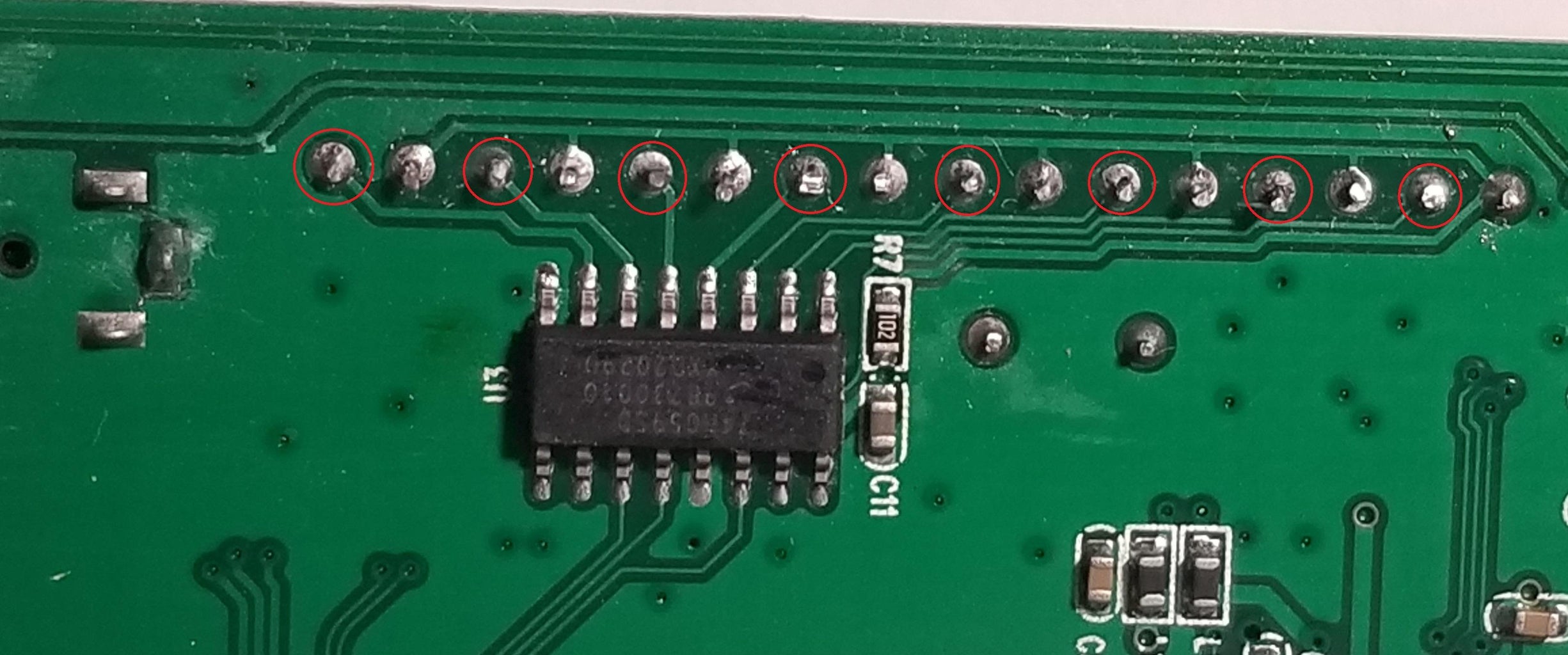
- Flip over the board and find the area where the green indicator LED's are soldered.
- Each LED will have 2 pins, you are going to need the ones that connect to the black chip. See image for the pins.
- Solder a wire to the correct pin of each LED.
- Flip back over the board and locate the pads for the barrel jack of the power input.
- Solder a wire to the 5v pad & 1 to a GND pad.
Step 5: Button Press(Soldering to Arduino)


- Solder the other end of the wire attached to the JTD-0801 5v pad to the 5v pin of the Arduino
- Solder the other end of the wire attached to the JTD-0801 GND pad to a GND pin of the Arduino
- Solder the corresponding wire attached to each LED indicator light to the corresponding pin on the Arduino. (See chart below). These pins are not required, you can use any ones, just make sure to change sketch accordingly.
- Solder the wire coming off the Input button on the JTD-0801 to the Collector pin of the transistor.
- Solder the Emitter pin of the transistor to any source of ground in the JTD-0801.
- Solder a wire from Pin 10 of the Arduino to 1 leg of the appropriate base resistor for your transistor.
- Solder the other leg of the resistor to the base pin of the transistor.
See images for wiring diagrams.
Indicator LED: Pin #
VGA 5
HDMI 1 4
HDMI 2 2
HDMI 3 3
AV 2 6
AV 1 7
Component 2 8
Component 1 9
Switcher Button 10
Step 6: Button Press(Arduino Configure)

- Open the attached Sketch JTDButtonPress.ino in the Arduino IDE.
- Edit any Pin numbers if you changed any.
- Upload the sketch to the Arduino.
- Open the Arduino IDE Serial Monitor & enter the corresponding number to the input you wish to change to. Consult the chart below for inputs.
InputNumber Entered:
VGA 0
HDMI 1 1
HDMI 2 2
HDMI 3 3
AV 2 4
AV 1 5
Component 2 6
Component 1 7
Standby Mode s
Attachments
Step 7: Additional Info
The above sketches just give a basic idea of what's possible. In my Instance I used a spare remote to control the JTD-0801. The process to configure this is a bit more advanced but I will include the sketch for those interested. The remote I used utilized the Sanyo protocol which is no longer supported in the I Remote library. An IR receiver connected to the Arduino is needed.
NOTE: The JTDButtonPressSerial.ino sketch uses an older version of the IRRemote library. The sketch can easily be converted to be compatible with the newer library version. I did not convert it as it is not likely the method used by most visiting this page.
Attachments
Step 8: Conclusion
Hopefully you found this useful! If there are any issues or if you have any questions leave a comment. Will try to help out.


