Introduction: Simon Says Game


Welcome to my Simon says game!!
This intractable will walk you through to create a Simon says game on tinkercad
Step 1: Materials

you will need the following equipment in tinker-cad:
4 push buttons
4 any colour LEDs
1 Piezo
1 Potentiometer
4 360 ohms resistors
4 1k ohms resistors
Step 2: Set Up Buttons

Start by placing the buttons along the middle of the breadboard. Add 2 wires to the breadboard so there is a ground and a rail with 5V as shown in the image.
Step 3: Add Resistors

Add the 4 1k ohm resistors to the breadboard and connect them to ground. Add power to the buttons as shown in the image above
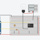
Step 4: Add Piezo and Potentiometer

Add the piezo and connect it to the potentiometer as shown in the image. This will allow the use of buzzer noises later in the game. I will flip the piezo in the next slide so do not panic if it looks a little bit different.
Step 5: Add LEDs

Add the 4 LEDs and make sure each LED is right beside a button so its easy for the user to understand which button activates each LED. Add each 360 to connect to the cathode of each LED and connect to ground.
Step 6: Add Wires to LEDs

Add wires to connect each LED to the Arduino so it can turn on in the game.
Step 7: Connect Wires to Buttons

Now connect 4 pins to each button as shown in the image. The orange wires is the wire that connects to the buttons. This pin will be used in the future.
Step 8: Code Part 1

The image shows the code required to run the game on the Arduino. Read the comments in the image to gain a better understanding of what each line does. Remember that my pins may be different then your setup so change that part of the code accordingly.
Step 9: Code Part 2

The image shows the code required to run the game on the Arduino. Read the comments in the image to gain a better understanding of what each line does.
Step 10: Code Part 3

The image shows the code required to run the game on the Arduino. Read the comments in the image to gain a better understanding of what each line does.
Step 11: Code Part 4

The image shows the code required to run the game on the Arduino. Read the comments in the image to gain a better understanding of what each line does.
Step 12: Code Part 5

The image shows the code required to run the game on the Arduino. Read the comments in the image to gain a better understanding of what each line does.
Step 13: Code Step 6

The image shows the code required to run the game on the Arduino. Read the comments in the image to gain a better understanding of what each line does. This is the last slide for the project and now when you run the program should run.
I hope you enjoyed it! :)