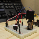
Introduction: Simple Camera Slider Electronics
Today we're building electronics for a simple slider, without using a stepper driver chip or breakout board.
Step 1: Parts List
We will need the following:
- Some Jumper Wires
- 1 x 10k Resistor
- 1 x Button
- 4 x 220 Ohm Resistors
- 4 x NPN Transistors (I've used the pn2222)
- 4 x LED's1 x 5v Unipolar Stepper Motor (I'm using the 28BYJ-48 Motor)
- A Breadboard and
- An Arduino.
Step 2: Breadboard and Schematics
The circuit is sectioned into 2 parts
- The Button Section and
- The Stepper driver section
Step 3: Button Section
- Connect the 2 negative rails of the breadboard to the ground pin of the Arduino,
- Then connect the 2 positive rails of the breadboard to the 5v pin of the Arduino.
Lets start off with the button section.
- Place the button on the breadboard (In the final slider there are 2 contact points that will be closed once the sliding unit reaches either end).
- Connect one end of the button to the positive rail.
- Connect the other end of the button to ground using the 10K resistor.
- Connect pin 3 of the Arduino to the intersecting point of the button and resistor.
Step 4: Stepper Driver Circuit
Now lets start building the stepper driver circuit
(It's important to note here that the transistors must be able to handle the max current draw of the stepper motor, you can find this info on the datasheets).
- Place a transistor on the breadboard
- For the pn2222 transistor the first pin is the Emitter, connect the Emitter pin to the ground rail.
- The collector is the 3rd pin on the pn2222, connect a lead to the Collector of the transistor and let it hang (We will be using this to connect the stepper motor later).
- The middle pin is the Base, connect a LED to the Base of the Transistor and another terminal strip.
- Connect one of the 220 Ohm resistors to the LED and to another terminal strip.
- Connect a lead between the resistor and the arduino.
Repeat this process until you have 4 of these "Electronic switches" connected to pins 5, 6, 7 and 8.
Step 5: Connecting the Stepper Motor
Moving on to the connection of the stepper motor.
- Connect a lead between the positive rail and the positive of the stepper motor.
- Connect the leads hanging in the breeze to the stepper motor.
- Ensure to connect the leads using the order found in the datasheet of the stepper motor.
Step 6: The Program
This program runs the stepper motor and decides what to do when the button is pressed.
The program continuously checks to see if the button is pressed.
The motor goes in one direction until the button is pressed down then the motor will reverse its direction and keep on going in that direction even when the button is released.
If the button is pressed again it will reverse its direction again.
In the motor control section of the program.
It follows a sequence of sending a signal to the pins on the arduino and in turn switch the LED's and Transistors on and off to make the motor step to that sequence.
I have designed this circuit and program with a chip called the ATtiny85 in mind hence it being such a simple and condense program
Attachments

Participated in the
Microcontroller Contest 2017


