Introduction: Simple, Cheap and Multiplatform Robotic Arm - Powered by Viper


Creates with Viper, a simple robotic arm with a Nucleo board, two servo motors and a cheap laser indicator. You can move the arm by writing the coordinates that express the degrees. For the comunication to the Nucleo board, you can use a serial port, and a simple Viper protocol. Follow the simple steps.
Materials
1 x Viper IDE (free)
2 x TowerPro SG90 9G Servo Motor($ 9,00)
1 x cheap laser pen ($ 5,00)
1 x 3D printed structure ($ 4,00)
Step 1: What Is Viper?

Viper is a a Python development suite that supports fast design and integration with sensors and cloud services (http://www.viperize.it). VIPER runs on all the 32bit ARM Pro and DIY microcontrollers like Arduino, UDOO, Particle, ST Nucleo. Viper start with a great Kickstarter campain.
Viper use a VIPER IDE, a multi-platform and browser-based developing environment with cloud sync and board management features.
Step 2: Download and Install the Viper IDE

Go to http://www.viperize.it/download/ and download the Viper. Is available also the Viper Google play App for Android (https://play.google.com/store/apps/details?id=thingsoninternet.biz.viperapp&hl=en)
Download the Windows, Linux and iOS installers from Viper Download page (security messages can be shown on Windows, please accept and go ahead, this issue will be solved soon). Install it and launch through the Viper shortcut Create a Viper user through the dedicated button. Check your email and verify your new account by clicking on the provided link. Once the account has been verified the Viper IDE automatically logs you into the Viper cloud (the first time you create a user account an IDE restart can be required. If you have sign-in issue please restart the IDE) To make the board usable, you need to Viperize it. Viperization is the process of installing the Viper VM on a board. The process can be launched by clicking on the dedicated button available on the Viper IDE top bar. Some boards require to be putted in upload mode, the IDE will guide you through the entire process
Don’t forget to install your boards USB drivers, downloading them from:
Arduino DUE driver page (https://www.arduino.cc/en/Guide/ArduinoDue)
ST Nucleo F401RE driver and firmware page (https://developer.mbed.org/teams/ST/wiki/Nucleo-Firmware)
UDOO board serial driver download page. (http://www.udoo.org/other-resources/)
Step 3: The Viper IDE

Viper is integrated with a dedicated development environment. The Viper IDE is a browser-based development environment that runs on Windows, Linux and Mac. Board Management Toolbar Through the Viper IDE Boards Management Bar all the connected devices can be managed. The Boards Management Bar can be used for Viperizing the connected boards by uploading on them the Viper Virtual Machine. Moreover, all the Viper supported boards are listed also if not connected as Virtual Boards allowing code verification for specific platforms without requiring physical connection.
When launched, the Viper IDE starts a Python local server that controls the connected peripherals showing all the available boards on the Boards Management Bar.
Step 4: Add Servo Motor Library

After the installation of Viper App, and the registration to community of Viper, you can install the Servo Motor Library. The Libraries are a pre-prepared code to simplify the use of determinate hardware, or particular functions. You can add the Library by the package menu.
You can search "Servo Motor Library", and after you can add this library to the Viper IDE. After you can use this library, on your project, by a simple line command. On the top of your code you can write:
from servo import servo
Step 5: Viperize the Nucleo and Upload the Code

Open the Viper IDE. After this operation, plug in the ST Nucleo. In the top menù choose ST Nucleo F401RE. Now you do the "viperization" of the board. For this you can press the Viper button. The viper button is near the shield menù, the symbol is the V of Viper. This operation is fully reversible. In other words you upload a new firmware on the board. Ok now you have a Viper board! For create a new project you can click the + (new project) on the Projects menù. Then copy the code of the code file, and paste it on the window. The Viper IDE save the project automatically. If you are a member of Viper community, then do you have a cloud space for your projects. You can reload this project by the cloud of Viper whenever you want by other computer in the world. Verify your project by clicking the verify button. If all is OK you can upload the code on the board, by pressing the upload button.
Attachments

Step 6: Serial Console and System Messages

The Viper IDE also includes a System Messages Panel on which all the compiler, debugger and server messages are reported. Moreover a Serial Terminal Console is also integrated in the right bar. The Viper IDE supports multiple Serial Terminal Console opened in parallel. Various projects output can be monitored from the same panel switching between the opened tab. When a Serial Terminal Console is opened it is automatically configured to open the serial port assigned to the selected board (USB OS assigned serial port). The IDE console baud-rate is set by default at different values depending on the selected board. The baud rate for a board is displayed during bytecode upload. This console has to be considered as an integrated debugging output to be used with the Viper default print function. To read a board serial port configured with a different baudrate an external serial port terminal like Putty should be used. Any other external port terminals can conflict with the Viper Serial Terminal Console. Users should close the Serial Terminal Console before launching any other external terminals.
Step 7: Connect the Wires


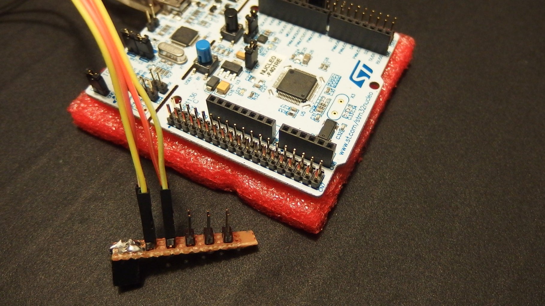


The connections of wires is very simple. You just plug the power source of Nucleo, in the servo motors, and connect the data port for the servo motor X and Y. The Nucleo port used for the servo motor control are D10 and D11. On the picture you can see a little handmade shield that multiply the power port of Nucleo. You can use also a breadboard for this. See the pictures for the installation.
Pay attention in this procedure. You can burn the servo motors or the Nucleo shield.
Ok now you have connect all the wires!
Step 8: Print the Pieces and Assembly the Structure


For the structure of the robotic arm you can print the piece of plastic that combines the two servo motors.
Download the structure from Thingiverse: http://www.thingiverse.com/thing:1274295 or print it by the 3Dhubs.
3DHubs is a community of 3D printers. Choose a 3D print of your zone and print the piece. The cost of printing are very cheap, because the piece is very little and simple.
For the materials of printing I prefer the abs or colorfabb xt filament for this work, because the PLA not is the first choose for this kind of pieces. In this case, in fact, the piece are functionally, and the plastic is under the vibrations that can break the structure.
Step 9: Use a Viper IDE for the Comunication

By the Viper app you can connect to the board by use a serial communication. After the opened the "serial" window, you can put the coordinates on the command line and click enter to send the numbers to the board. Express the coordinates in degrees. From 0 to 180 degrees. If you use the 0, the motor go to the 0 position, and switch off the circuit of the servo.
Wait the start signal: All servo ON
Then write the numbers of degrees from 0 to 180.
Step 10: Final Result


Now you have a robotic arm! In this case the arm moves a laser pen. You can use this arm for every kind of operation you can imagine. Plug in the board on the computer, open the serial port, and put inside the coordinates for X and Y axis. Choose the X and Y coordinates between 0 and 180 degrees.
The arm moves the laser on the coordinates that you have chosen. Remember if you use the 0, the motor go to the 0 position, and switch off the circuit of the servo.