Introduction: Snapdragon
This instructable was created in fulfillment of the project requirement of the Makecourse at the University of South Florida (www.makecourse.com). This project is a fun skeletal dragon that opens its mouth to scare you off when you approach, and if you put your fingers in its mouth it will try to snap them off!
Step 1: Gather Materials
Electronic components
-1 Arduiino Uno R3
-1 USB cable
-1 Ultrasonic Range Module
-1 Touch Sensor Module
-1 SG90 9G servo
-1 Breadboard
-Jumper cables, various lengths
-10 pin female-to-female Dupont cables
-EL wire*
Other
-1 Electronics Enclosure
-1 Dowel
Tools
-Super glue
-Electric Drill
-Small screwdriver
-Something to trim the dowel
*NOTE: The interference caused by the EL wire has not been adjusted yet at the time of publishing this, so the EL wire is not powered nor connected to the breadboard in this intractable. This will be remedied in the next few weeks and an updated version published.
Step 2: 3D Print Parts
29 pieces were printed for this project, 22 vertebrae and 7 other pieces. Less or more vertebrae could be printed depending on the desired look, just keep in mind the length of the wires required to run through the length of the spinal column. Print the attached pieces and assemble them as described in Step 4.
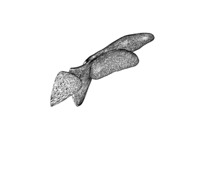
The head is printed in two mirrored halves,
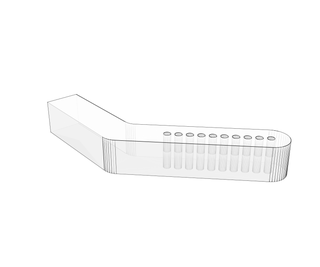
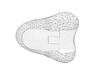
The jaw is comprised of two pieces, one to hold the touch sensor, and one to attach to the servo,
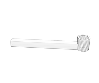
The servo is attached to the head with a piece, the dowel supports the head with a piece, and the dowel is held in place on the base with another piece.
Attachments
Step 3: Wire
Step 4: Assemble
The assembly is delicate work. It consists of joining the 3D printed parts, preparing the electronics enclosure and placing the wires correctly within the parts of the piece. Be careful not to pull any wires loose while threading them through the vertebrae.
PREPARING THE ELECTRONICS ENCLOSURE
1) Flip the enclosure over so that the lid is the base of the piece
2) Find the center of what is now the top of the box and drill a hole large enough to accommodate the dowel and some wires.
3) Drill a hole in the center of the front of the box to allow for the proximity sensor
4) Drill a hole in the lower right corner of the back of the box to allow a USB cable to exit the enclosure
JOIN THE 3D PRINTED PARTS
1) Join the two halves of the head together with superglue
2) Join the two support pieces to the head
3) Join the two jaw parts together
4) Screw the arm of the jaw into the horn of the servo and insert the servo into its holder with the screw that came with the servo
5) Glue the dowel base to the inside of the lid (which is now the base) of the electronics enclosure
WIRES
1) From the bottom up, thread the EL wire through the right side of the vertebrae like you would with beads on a necklace. Once all the vertebrae are on the EL wire, thread the EL wire down the left side of the vertebrae, forming a loop of wire at the top.
2) The 3 wires leading to touch sensor and the 3 wires leading to the servo need to be threaded through the drilled hole in the enclosure then the central holes of the vertebrae. Female-to-female dupont cables in matching colors should be used to extend these wires.
DOWEL PLACEMENT
This step could be a little tricky, and an extra set of hands to hold the piece while you insert the dowel would be beneficial.
1) Insert one end of the dowel into the piece supporting the head, some sanding may be required.
2) Pass the dowel through the hole in the box and Insert into the dowel base that is glued to the lid base.
Step 5: Code
You will need to download the library "NewPing" for the proximity sensor. This can be found here: http://playground.arduino.cc/Code/NewPing
The code "Snapdragon" is attached, as well as a video explaining the function of the code.


