Introduction: TMP36 Temperature Sensor With Arduino in Tinkercad


In this project, you will turn the Arduino into a thermometer! Use a temperature sensor to measure your skin temperature, and register the output with three LEDs. Even though the Arduino is a digital tool, it can interpret signals from an analog input, like the TMP36 temperature sensor, using the built in Analog-to-Digital (ADC) converter, accessed through the analog pins A0-A5, which you may have learned about in a previous lesson about analog input.
Explore the sample circuit embedded here by starting the simulation, clicking on the sensor, then dragging its temperature slider to adjust the simulated input and observe the resulting LED patterns.
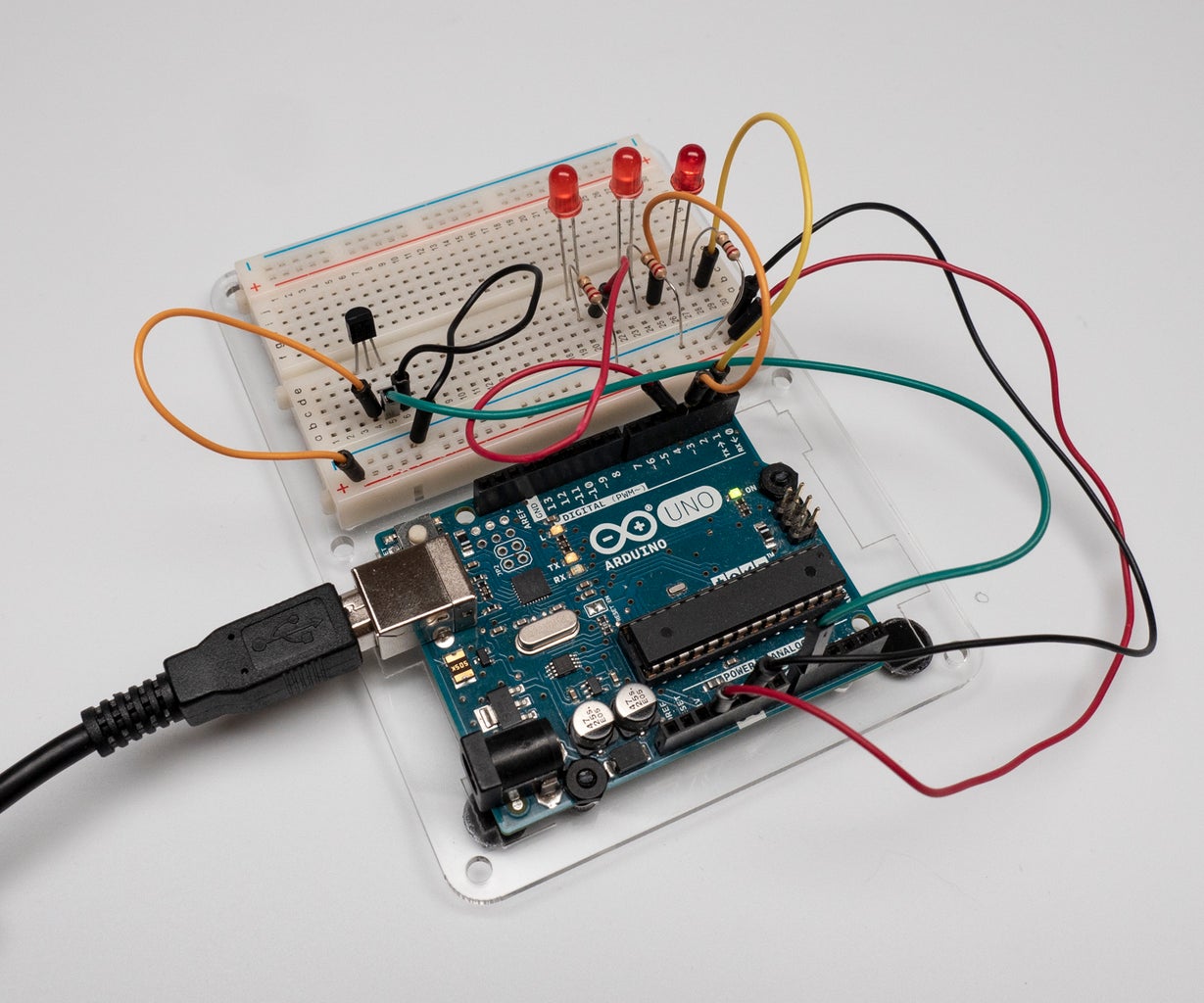
In this lesson, you'll build this simulated circuit yourself along side the sample. To optionally build the physical circuit, gather up your Arduino Uno board, USB cable, solderless breadboard, three LEDs, three alike resistors (any value from 100-1K, 220 ohms preferred), a TMP36 temperature sensor, and breadboard wires.
You can follow along virtually using Tinkercad Circuits. You can even view this lesson from within Tinkercad (free login required)! Explore the sample circuit and build your own right next to it. Tinkercad Circuits is a free browser-based program that lets you build and simulate circuits. It's perfect for learning, teaching, and prototyping.
Step 1: Build the LED Circuit

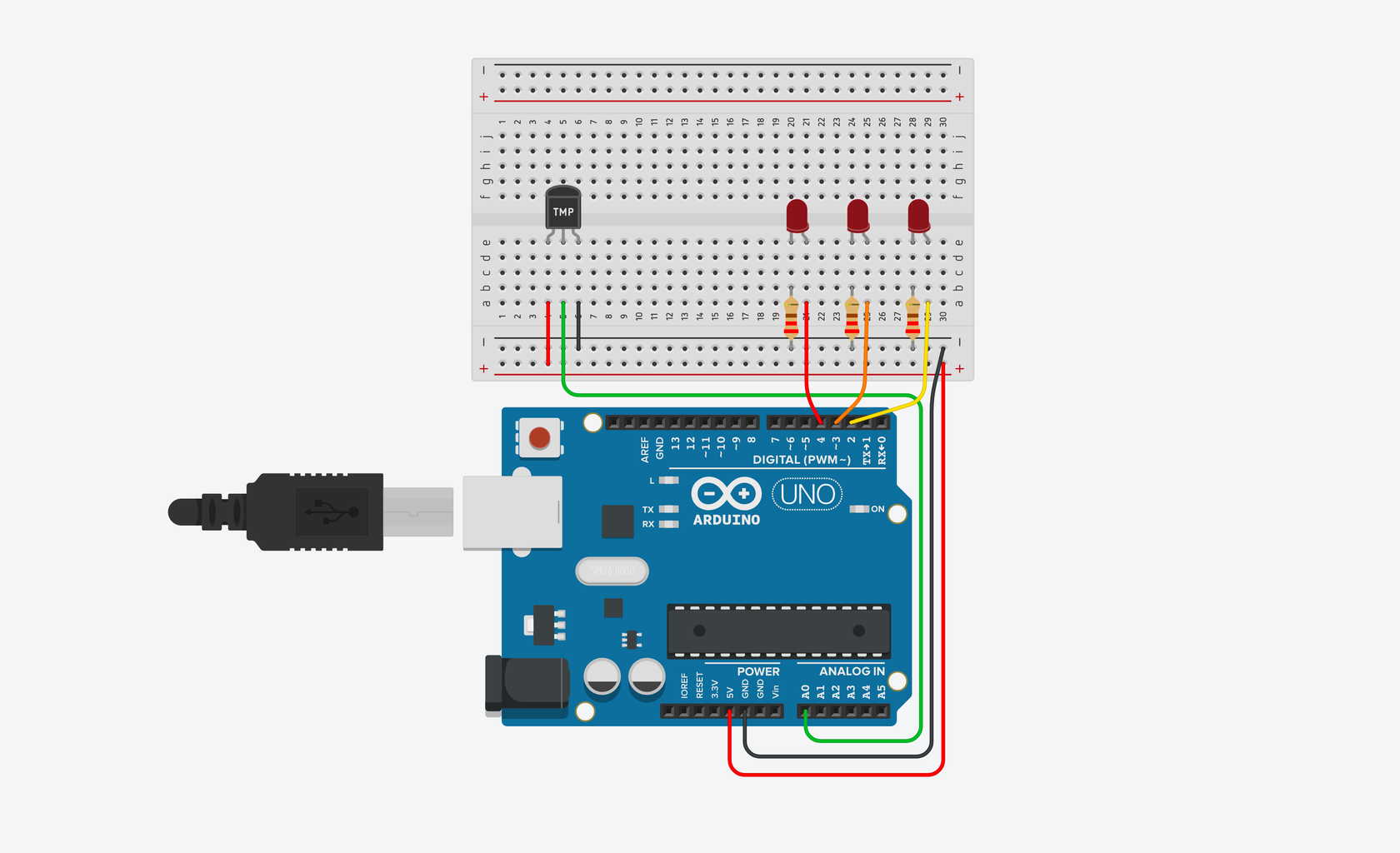
Just as you’ve learned from the introductory lessons, start by wiring up your Arduino and breadboard with power and ground next to the example circuit, then add the the three red LEDs to the breadboard, as shown. These will be the indicator or "bar graph" lights for the project.
Drag an Arduino Uno and breadboard from the components panel to the workplane, next to the existing circuit.
Connect the 5 volt and ground pins on the Arduino to the power (+) and ground (-) rails on the breadboard with wires. You can change the wire colors if you want to! Either use the inspector dropdown or the number keys on your keyboard.
Drag three LEDs on the breadboard in row E, spaced 2 breadboard sockets apart. You can change the LED color using the inspector that pops up when you click on each one.
Use a 220 Ohm resistor to connect each LED's cathode (left leg) to the ground rail (black) of the breadboard. In Tinkercad Circutis, you can change a resistor's value by highlighting it and using the dropdown menu in the inspector.
Connect the LED anodes (right, longer legs) to digital pins 4, 3, and 2 on the Arduino. The LED anode (+) is the terminal that current flows into.
The cathode (-) is the terminal that current flows from. This connects to the ground rail.
Step 2: Add Temperature Sensor
A temperature sensor creates a changing voltage signal depending on the temperature it senses. It has three pins: one that connects to ground, another that connects to 5 volts, and a third that outputs a variable voltage to your Arduino, similar to the analog signal from a potentiometer.
There are several different models of temperature sensor. This model, the TMP36, is convenient because its output voltage is directly proportional to temperature in degrees Celsius.
In the circuits editor, find the temperature sensor in the components drawer.
Place the temperature sensor (TMP36) on the breadboard with the rounded part facing away from the Arduino, as shown in the figure (this is the default orientation).
Place the temperature sensor on the breadboard in row E, as shown.
Wire up the temperature sensor so the left pin connects to the 5V voltage rail, the center pin connects to A0 on the Arduino, and the right pin connects to the GND rail.
Step 3: Analog Input Observation


In the circuit schematic, you can see that the temperature sensor is connected to power (5 volts) and ground (0 volts) and the analog pin A0. As temperature rises, the pin connected to A0 increases its voltage. You can also see that three LEDs are each connected to their own digital pin.
Even though the Arduino is a digital tool, it’s possible for it to get information from analog sensors to measure things like temperature or light. To do this, you’ll take advantage of the Arduino’s built-in Analog-to-Digital Converter (ADC).
Analog-in pins A0 to A5 can interpret voltages between 0 and 5V, and translate that voltage to a value between 0 and 1023 for the Arduino sketch to use. The analog pins are primarily used to read information from sensors (but can also be used as digital outputs 14-19, unrelatedly).
Click "Start Simulation."
Open the Code Editor and find the "Serial Monitor" button to watch the sensor values pour in.
Step 4: Blocks Code
Let's use the code blocks editor to listen to the state of the sensor, then make decisions about which LEDs to light up based on the sensor's value.
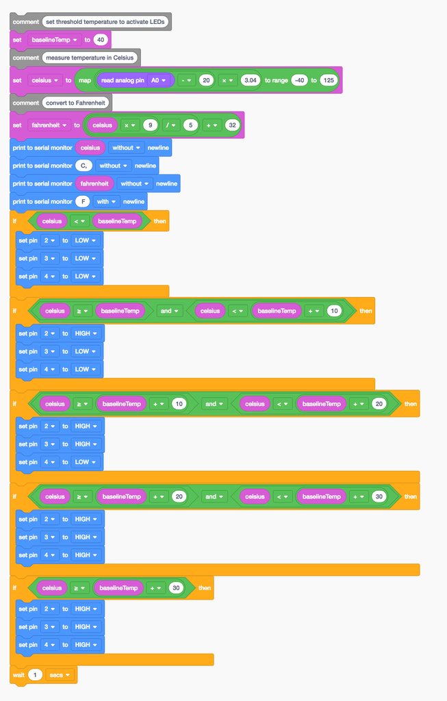
Click the "Code" button to open the code editor. The grey Notation blocks are comments for making note of what you intend for your code to do, but this text isn't required or executed as part of the program.
Click on the Variables category in the code editor. Create a new variable called baselineTemp and use a "set" block to set it to 40 (degrees C).
To store the sensor value, create a variable named "celsius".
Drag out a "set" block and adjust the dropdown to our new variable celsius.
In the Math category, drag out a "map" block, and nest two arithmetic blocks ("1 + 1") within its first field.
Adjust the range from -40 to 125.
Click on the Input category and drag out an "analog read pin" block, and place it into the first arithmetic field inside the "map" block.
Adjust the arithmetic blocks to "(read analog pin A0 - 20) x 3.04".
Optionally create a new variable for converting the temperature to Fahrenheit with a set block and some arithmetic blocks to read "set fahrenheit to (celsius x 9)/5 + 32".
Add some serial monitoring blocks to print out the temperature in one or both C or F.
Click the Control category and drag out an if then block, then navigate to Math and drag a comparator block onto the if block.
In the Variables category, grab the celsius variable and the baselineTemp variable and drag them into the comparator block, adjusting the dropdown so it reads "if celsius < baselineTemp then".
Add three digital output blocks inside the if statement to set pins 2, 3, and 4 LOW.
Duplicate this if statement four times and add arithmetic blocks and and/or blocks to create five total state detection if statements. The first state is "the temperature is below our target baseline" so no LEDs light up. When the temperature is greater than or equal to the baselineTemp and less than baselineTemp+10, light up only pin 2's LED. When the temperature is between baselineTemp+10 and baselineTemp+20, light up two LEDs. And so on to account for all the desired states.
Step 5: Arduino Code Explained

When the code editor is open, you can click the dropdown menu on the left and select "Blocks + Text" to reveal the Arduino code generated by the code blocks. Follow along as we explore the code in more detail.
int baselineTemp = 0;
int celsius = 0;
int fahrenheit = 0;
Before the setup(), we create variables to store the target baseline temperature, as well as the sensor value. They're called int because they are integers, or any whole number.
void setup()
{
  pinMode(A0, INPUT);
  Serial.begin(9600);

  pinMode(2, OUTPUT);
  pinMode(3, OUTPUT);
  pinMode(4, OUTPUT);
}
Inside the setup, pins are configured using the pinMode() function. Pin A0 is configured as an input, so we can "listen" to the electrical state of the temperature sensor. Pins 2, 3, and 4 are configured as outputs to control the LEDs.
void loop()
{
  // set threshold temperature to activate LEDs
  baselineTemp = 40;
  // measure temperature in Celsius
  celsius = map(((analogRead(A0) - 20) * 3.04), 0, 1023, -40, 125);
Anything after a set of slashes // is a comment, just for us humans to read, and is not included in the program when the Arduino runs it. In the main loop, baselineTemp is set to its target 40 degrees C.
  // convert to Fahrenheit
  fahrenheit = ((celsius * 9) / 5 + 32);
  Serial.print(celsius);
  Serial.print(" C, ");
  Serial.print(fahrenheit);
  Serial.println(" F");
The formula for converting between celsius and Fahrenheit is F = (C * 9) / 5 + 32. Printing to the serial monitor helps you observe the temperature change more granularly than the LED states show alone.
  if (celsius < baselineTemp) {
    digitalWrite(2, LOW);
    digitalWrite(3, LOW);
    digitalWrite(4, LOW);
  }
  if (celsius >= baselineTemp && celsius < baselineTemp + 10) {
    digitalWrite(2, HIGH);
    digitalWrite(3, LOW);
    digitalWrite(4, LOW);
  }
  if (celsius >= baselineTemp + 10 && celsius < baselineTemp + 20) {
    digitalWrite(2, HIGH);
    digitalWrite(3, HIGH);
    digitalWrite(4, LOW);
  }
  if (celsius >= baselineTemp + 20 && celsius < baselineTemp + 30) {
    digitalWrite(2, HIGH);
    digitalWrite(3, HIGH);
    digitalWrite(4, HIGH);
  }
  if (celsius >= baselineTemp + 30) {
    digitalWrite(2, HIGH);
    digitalWrite(3, HIGH);
    digitalWrite(4, HIGH);
  }
  delay(1000); // Wait for 1000 millisecond(s)
}
The loop's six if statements evaluate for different segments of a certain temperature range between 40 and 46 degrees C, lighting up more LEDs the warmer the temperature.
If you want to see a more obvious change in bar graph lights, you can change the baseline temperature variable and/or the range that you are looking at by changing the arguments in the if() statements. This is called calibration.
Step 6: Use It!


If you built a physical version of this circuit, you can try it out with the Arduino software's serial monitor (magnifying glass button in the upper right of the sketch window), activating the sensor with your fingers. The project might not do what you want it to if the room temperature is really cold or really warm, or if your fingers are cold!
If using a physical board, observe the room temperature using the serial monitor, and set baselineTemp to that value.
Adjust your different temperature threshold "buckets" to a smaller range (2, 4, 6, instead of 10, 20, 30).
Upload your code again, and try holding the sensor in your fingers. As the temperature rises, you should see the LEDs turn on one by one.
Step 7: Next, Try...
You have used analogRead() and the serial monitor to track changes inside your Arduino and create a simple temperature display with LEDs. You will use this technique with other types of sensors in future projects! One way to expand this project is to create a way for two people to compare finger temperature. Would you need two sensors, or could they take turns? How would you build code to function as well as communicate the way to use it?
You can also learn more electronics skills with the free Instructables classes on Arduino, Basic Electronics, LEDs & Lighting, 3D Printing, and more.


