

Introduction: The Anything Clock


Hi, my name is Ridhwan Aggarwal and I am currently a student studying in India. I made a clock, with a revolving magnet on the inside, letting any other magnet object be attached on the outside. It uses gear to modify the rpm of the motor inside, eventually rotating a ring gear and spinning the magnet. The magnet shows the seconds of the time, while the lights on the outside show the minute and hour.
Supplies


Hardware and Electronics
Neopixel (144 Led's per meter)(120 Led's to be used)
Bearing 12x16mm (Roller)(4)
Bearing 8x5mm (Ball)(1)
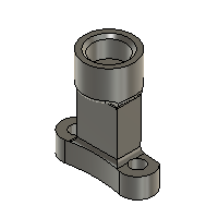
BO Motor (single-shaft)(1)
Seeed Studio SAMD21 (Micro-Controller)(1)
Wires (5)
3x6mm screws (2)
2x12mm screws (2)
6x8mm magnet (1)
3D Printed Parts
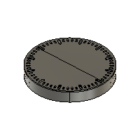
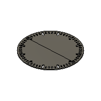
Clock base (2 Parts)
Clock top (2 Parts)
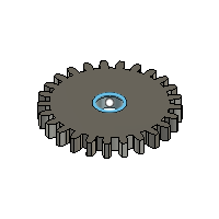
Spur ring gear (1)
Internal spur gear type 1 (1)
Internal spur gear type 2 (1)
Connector for Magnet and Spur Ring Gear (1)
Translucent minute inserts (48)
Translucent hour inserts (12)
Tools
Screwdriver (1)
Gel based super-glue (1 Bottle)
Soldering Iron (1)
Solder (1 Spool)
Step 1: 3D Designing


I designed the entire clock on fusion and have attached the download files below. The overall idea of the clock was to show time using LED's, as well as a central magnet which spins, allowing any other magnetic object to be attached to it, acting as the second hand of the clock. The LED's show the minute and hour, through a neopixel.
Attachments


Step 2: Printing the Parts


After designing the parts, I started with printing them using my Bambu labs A1. I carefully sliced all the parts in the Bambu slicer, giving them all optimal strength and supports. Above are images of the printed parts.
Step 3: Assembly of Clock


Gear & Base Assembly
- Screw the spur gear and magnet connector together.
- Apply glue inside the connector cavity and insert the 6×8 mm magnet.
- Glue both base plates together to form the main clock body.
- Insert the roller bearings onto the four corner cylinders.
- Place the ball bearing on the smaller cylinder.
- Add the middle gear on top of the ball bearing.
- Install the small motor gear onto the motor shaft
- Attach the BO motor to its mount using 2×12 mm screws
- Place the ring gear inside the roller bearings and ensure it meshes with the middle gear.
Electronics & Wiring
- Stick the NeoPixel strip along the inner edge of the clock frame.
- Connect three wires to the NeoPixel: positive (bottom pad), ground (top pad), and data (middle pad).
- Solder the NeoPixel wires to the microcontroller: VCC, GND, and pin 6 for data.
- Connect two wires to the BO motor terminals and solder them.
- Connect one motor wire to VCC and the other to GND.
Programming
- Plug the microcontroller into your computer using a USB cable.
- Open Arduino IDE, select the SAMD21 board, paste the code, and click Upload. (Attached Below)
- Find the "set time here!!'' comment and change the time to your current time.
Finishing Touches
- Apply small dabs of glue and insert the translucent hour and minute markers into the holes.
- Attach the top cover using tape or non-permanent fasteners for easy maintenance.
Step 4: Code
Step 5: Functionality
The two videos above show the functionality of the LED lights, one displaying the Hour and the other displaying the minutes, in this case, it would be the red one showing hours and green showing minutes.
(The LED's are a bit less visible in the video but I can assure you they are clear in real life)
The video attached above also shows moving objects such as a resin printed design, a benchy and even a pawn chess piece. These all are containing of magnetic components therefore acting as the second hand of the clock. Similarly anything with a decently strong magnet or with one attached to it can repeat the same motion.
Step 6: Conclusion
I hope that the following steps and instructions help you to make your very own clock. I really wish that your enjoyed reading and making my Instructable and I wish you a great day.
