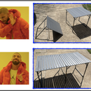
Introduction: The Eratosthenes-inator
I am a high school astronomy teacher. Every year I have a few students tell me that they think the Earth is flat. I'm pretty sure they are joking, but I genuinely appreciate those students because they provide a great stepping off point for a discussion about how science works and the importance of evidence-based claims.
If I just explain to students how we know the Earth is round, it comes down to whether or not they believe me versus someone on the internet.
Also, the tricky part about astronomy is that the objects and phenomena we study are very big and/or very far away and/or unfold over very long stretches of time. Making astronomy a hands on class is challenging.
I wanted to come up with a direct and hands-on way for students to observe the evidence that supports the claim that the Earth is round. Enter...
... the Eratosthenes-inator!
A device that will...
1) demonstrate evidence used to support the claim that the Earth is a sphere
2) re-create the method used to measure the circumference of the Earth
3) demonstrate the way stars can be used to determine one's location on a spherical Earth
A quick note about the name ...
- Eratosthenes was a Greek scientist who first measured the circumference of the Earth using the method we will use. Here's a link to more information about him.
- the "-inator" is a nod to the great scientist and engineer Dr. Heinz Doofenshmirtz of Phineas and Ferb.
Supplies
- 1 of ... 2x6 8’
- 1 of ... 12” x 42” white tile board (.25” thick) ... comes in 4'x8' sheets
- 8 of ... 1.25” drywall screws
- 10 of ... #8x1” flat head wood screws
- 10 of ... #8 finish washers
- 2 of ... 4.5” hex head bolts
- 2 of ... neodymium disc magnets (5mm diameter)
Tools & building supplies
- butcher paper (for making cut templates)
- band saw or jigsaw
- drill
Step 1: Making the Curved Sides Template
- On a piece of butcher paper, draw a line 1 meter long
- Draw two intersecting arcs 1 meter from the endpoints of the 1-m line.
- Draw an arc across the original 1 meters line, centered on the intersection in step 2
- Cut out the enclosed arc
- tape the arc to the 2x6 and use it to sketch the curve
The maximum height of the curved arc will be the same as the width of the 2x6 (which is 5.5" or 14 cm). If it is a little to tall or short, slide it so the top of the arc is at one edge of the board and the flat bottom is parallel to the other edge of the board. When you're using this in class, it's only the radius of the curve that really matters.
Step 2: Cutting the Curved Sides and End Supports
- Trace out the cut paths on the 2x6 ... If you arrange them as shown in the image above you will need only one 2x6.
- Use a band saw or jigsaw to cut out the curved pieces.
- Stack them and sand both curved edges to get a matching smooth curve.
Cut a 1-ft section from the remaining 2x6. Rip this in half to make two 1’x1-3/8”x2-5/8” pieces.
Step 3: Assemble the Sides and Supports
Use wood glue and drywall screws to attach the supports to the ends of the curved sides.
Note: I recommend drilling pilot holes for the drywall screws. The tapered end of the curved side is susceptible to splitting. Glue and a nail gun could be used instead.
Step 4: Prepping the Curved Top
- Cut a 12" x 42" section of the tile board panel
- Drill 1/8" holes at the locations shown in the image. The holes should be 3/4" in from the edges.
Step 5: Attach the Curved Top and Hex Bolts
- Use the #8x1” wood screws and #8 finish washers to attach the panel to the top of the curve sides.
The 4.5” bolts are held by the 1/2” neodymium magnets under the tile board. This enables them to be moved anywhere on the curve.
NOTE: I recommend not gluing the panel to the curved edges. Using whiteboard material enables students to mark measurements and make annotations. If the surface gets damaged over time it can be replaced if it is not glued down.
Step 6: Lesson Plan Part 1 - the Earth Is Round!
One piece of evidence that was used to determine that the Earth is round was the observation of ships traveling over the horizon. Instead of graduating becoming smaller and smaller as they would on a flat Earth, ships disappear from the bottom up as they go over the horizon. Here's a photograph of this phenomenon in real life.
This can be demonstrated by observing the Eratosthenes-inator from one of the short ends and moving an image of a ship from that end to the other.
What the observer will see is shown in the images above.
Step 7: Lesson Plan Part 2 - Measuring the Circumference of the Earth (BACKGROUND)
About 2000 years ago a Eratosthenes - a scientists living in Northern Egypt - developed a way to measure the circumference of the Earth.
There was a city in Southern Egypt called Syene at the time of Eratosthenes. From historical records he learned that on one day of they year at noon the sun is directly overhead when viewed from Syene. Today we know this occurs because Syene is located on the Tropic of Cancer and on June 22 the sun is directly over this line of latitude.
Eratosthenes lived in Alexandria - a city on the Mediterranean Sea several hundred miles north of Syene. At noon on June 22 the sun is not directly overhead when observed from Alexandria.
Eratosthenes was able to use the length of shadows made by a tower in Alexandria to determine how many degrees around the curved Earth there are between the two cities. With this knowledge and a measurement of the distance between the two cities he was able to use the proportional relationship below to calculate the circumference of the Earth.
Here are a few videos that explain this:
Step 8: Lesson Plan Part 2 - Measuring the Circumference of the Earth (PROCEDURE)
- Lay the Eratosthenes-inator on its side on a table. Use the magnets to hold the two hex bolts to the curved surface and place them about 50 cm apart. One of these represents a tower in Syene, the other a tower in Alexandria.
Place a 60 W bulb light source on a table at least 10 meters away. Turn off the room lights so this bulb is the only source of light.
Arrange the Eratosthenes-inator and/or the bolts so that one casts no shadow and the other does. See the image above.
Use a whiteboard marker to trace the length of the shadow.
With the room lights back on, use the length of the shadow and height of the tower at Alexandria to determine the arc-angle between the two cities. Measure the distance between the cities. Then calculate the circumference and radius of the entire circle the arc is a part of.
The dimensions used to construct the Eratosthenes-inator result in an end-to-end arc of 60º. This means that if you build six of them they can be arranged in a way that creates the entire circle - as shown in the image above.
Step 9: Lesson Plan Part 3 - Navigating With the Stars
Polaris (the North Star) has been used as a navigation tool by seafarers for centuries. It is used is not just to determine which way is North, but also to measure exactly how far North of the equator they are.
The Eratosthenes-inator can be used to demonstrate this. As shown in the image, protractors and drinking straws are attached to the hex bolts with rubber bands. The straws are arranged to point vertically upward.
The straw/protractor at the top represents the North Pole - Polaris is directly above an observer here.
The other straw/protractor represents an observer at some latitude North of the Equator. The angle this straw makes with the horizon (θ) can be measured with the protractor as shown.
The relationship between the altitude of Polaris and latitude can be demonstrated by sliding this hex nut up or down the arc and re-adjusting the straw to vertical. As the observer gets farther from the North Pole, Polaris gets closer to the horizon.

First Prize in the
STEM Contest


