Introduction: The Torsion Wire Magnetoscope


The torsion wire is a fascinating thing. I think it has some kind of genius to use the mechanical torque of a twisted wire to create a small restoring force for measuring weak physical values. This shows me how ingenious the scientist were back in the time when you had no electronic amplifiers, noise filters and computational statistical analyzers. I already used this principle successfully in my electroscope i already described at instructables. The application described here i even designed before i did the electroscope instruction. Originally my imagination was fueled by the work of Gauss and Weber, two german scientists who founded the magnetic association Magnetischer Verein(german) around 1836 in Göttingen. They invented a magnetometer to get absolute readings of the earths magnetic field fluctuations and did the first worldwide geomagnetic survey in history that produced also the first geomagnetic maps of the earth. All this was done without electronics, internet and satellites and exchanging measurement data by letter in written form. What a marvelous achievement!
The 2nd picture shows my first idea. I made a boom out of wood and hanged-in a aluminum rod with one neodymium magnet at each end, all oriented in the same way. It was principally nothing more like a thick compass needle with a pointer fixed at right angle. The little drawing shows the working principle. The rod turns around a virtual axis that runs through the middle between the two torsion wires. So it's not the torsion principle from my electroscope because the wires are not twisted around their own axis instead they are bent around each other! In this configuration the influence of static or quasi-stationary errors like temperature torque or material degrading of the wires are cancelled out. You don't have to zero the pointer arrangement like you need to do with only one torsion wire. That was one of the greatest improvements Weber invented for this magnetometer. By turning the hanger of the wires you can apply a good adjustable restoring force. You get good readings when you bias the torque in a way that the magnet rod is situated by around 45° deflection against the north-south direction of the geomagnetic field.
A little counterweight made out of lead and screwed to the backside of the pointer assembly was used to balance out the whole thing. That's what i used for testing and discovered that this configuration was much more sensitive than a simple compass! This is caused by the strong neodymium magnets that provide a strong torque of the geomagnetic field. Second. there is practically no friction and a very weak restoring force from the torsion wires.
This instruction is not a step by step approach to a fully developed device. Also for me it is still under testing and improvement. But i will show you the idea behind it and how to take care of the most crucial steps so you can build one of your owns. I named my device "magnetoscope" and not "magnetometer" because it doesn't provide absolute readings but relative fluctuations of the environmental field.
Step 1: Materials
I made my magnetoscope entirely from scrap and parts from hardware stores. There is nothing special in it. A rough list of materials is as follows.
- sheets of 4mm plywood
- timber beams 16x16mm
- two 5mm cylindrical neodymium magnets 10mm long
- aluminum rod 6mm and 10mm diameter
- aluminum tube 8mm outer diameter, 6mm inner diameter
- Small wooden ball 30mm diameter
- nylon wire
- a steel needle
- paper
- anodized iron wire
- 30mm long brass screw M3
- small glass tube 1mm inner diameter
The tools i used were
- Bucksaw
- lathe
- drilling machine
- table-stand buzz-saw
- file
- glue
But you also may use simpler tools. I want to encourage you to make your own design because the principles are simple as you'll see.
Step 2: Make the Base Arrangement and Pivot


I used a piece of the 10mm aluminum rod and cut it on my lathe to about 30mm length. I drilled a 0.8mm hole in the middle of one end to take-in the steel needle that was fixed with a drop of super-glue. On the other end of the rod i drilled a 2.5mm hole and cut a M3 thread into. I made a wooden base arrangement of roughly 24cm x 19cm. The pivot is screwed to the base.
Step 3: Construction of the Magnet Pointer Unit


This is the most crucial part. This assembly contains an aluminum rod of 55mm length and 6mm diameter. One small neodymium magnet is super-glued to one end each. Take care both magnets are oriented in the same N-S direction! I drilled one hole with 2.5mm diameter in right angle through the middle of the rod. It takes the small glass tube. I melted one end of the tube so that it got closed but this is just eye candy and not functional because the magnet rod must not sit on the needle pivot, otherwise we'd have too much friction.
I drilled two holes 2.5mm apart from the center with 0.8mm diameter through the rod where the torsion wires will run through. The distance between the two outer holes then is 5mm.
A 1mm hole was drilled in right angle to the others in the middle to take the iron wire as the pointer.
Last but not least another 2.5mm hole was drilled on the opposite side of the pointer and a M3 thread cut in. A 30mm brass screw without head is screwed into the rod and fixed with super glue. It will take a peace of lead as a counterweight for the pointer.
Step 4: Construction of the Boom and Wire Hanger


On my lathe i cut away 1mm diameter from one end of a 63mm long aluminum rod with 6mm diameter. This is not committing. I just did it to give the torsion wires equal spacing on the hanger and on the pointer. But 1mm difference is of absolute no relevance, so you can skip this step safely if you don't have a lathe.
Drill a 0.8mm hole through the end of the rod. It will take the torsion wires. At the other end i drilled a 3mm hole right through the rod. A small piece of a brass rod with 3mm diameter is pushed through the hole. The ends are cut so they stand out 4mm on each side. This is a detent for the wooden ball which will serve as an adjusting knob. The ball will get a 6mm drilling hole and rectangular angled filed-in trenches to slide over the detent.
I used 16mm x 16mm timber beams to construct a boom of 24cm height and 11cm width. An 8mm hole through the cross beam takes a piece of 8mm aluminum tubing that acts as a bearing for aluminum rod. You see i filed a gap into the tube that is covered by a small rubber ring. The rubber gives some friction on the rod while turning so that it is protected against unintended changes.
Step 5: Mounting the Torsion Wires and Casing


This is the trickiest part. Cut a piece of nylon wire (approx 50cm) from the coil. Then you need two small beads with a hole from a crafts shop. Lead one end of the nylon wire through a bead and make a knot. Fix the knot with super glue. The bead shall prevent the knot from slipping through the holes on the magnet rod.
Run the nylon wire, with the end without the bead, through one of the holes on the magnet rod until the beads sits tightly under the hole. Then route the wire upwards to the hanger and run it through the 0.8mm end hole. Route the wire down again through the 2nd hole on the magnet rod. Now make an open knot through the 2nd bead. Take a tweezers and carefully adjust the wire length so that finally the pointer turns easily around the pivot needle without sitting on its tip. When everything fits nicely pull the knot tight and protect it with a drop of super glue.
We need to built some kind of casing around the whole arrangement in order to protect the pointer from moving air. I used plywood sheets mounted across the rims of the wooden base to construct a casing and a removable lid.
I created a simple scale with a plywood base glued to the casing and a strip of paper. The scale was labeled in degrees by use of a set square with 0 in the middle and positive/negative degrees on the sides. The lid contains a piece of plexiglass, so you're able to see the scale even the lid is closed. A LED powered by 3 NiMH cells and a switch on the outside can give you some light on the scale while reading the values.
Step 6: Testing


OK, now everything is ready we can do some tests. The problem is that operating this device is time consuming. 200 years ago Gauss and Weber established a measurement process that required a lot of discipline from the user. He needed a clock and in exact time slots had to do the readings and write them in a log. If you wanted to get a series of values over one day in 10 minutes you were busy the whole day.
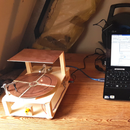
I decided to ease this pain and constructed a holder for my old Motorola MotoG smartphone i use for experiments. I wrote an app that takes a photo automatically in random intervals and transferring it to my FTP-Server. So i could collect the data. In Gimp i loaded the photos and made a small gif animation from it. Additionally i took the readings and wrote them into a gnuplot data file for displaying a chart with results.
The next thing to specify was the location to put the magnetoscope for measurement. Any place in my flat was too much contaminated by field distortions caused by magnets as components in household devices and the abundant use of iron in the building structures. After some testing i decided to put the scope in my attic. It was high enough above, at least the majority, of magnetic contamination. But even at this optimized place you couldn't expect to read the fluctuations of earths magnetic field. See the exemplified animation in the photo section. You see that there are really some changes going on during one day!
Looking for something to compare
To at least get some kind of reference to compare the quality of the readings with something reliable i stumbled across the very good website of Intermagnet an international geomagnetic survey organization that provides it's data for free! The geomagnetic measurement stations are scattered all around the planet and structured by a unique IAGA code. This is something like a locator. The nearest station to my hometown for example is Wingst( located roughly 50 miles northwest from my place) with the IAGA code "WNGST". You can get the HDZ-readings (horizontal field, declination and field strength in z-dimension which is right angled to the earths surface). See the data plots for the time frame i used for my measurements. The first diagram is a printout of the original Intermagnet data gathered for the same time-frame i used for my measurements (09-05-2018 18:00 - 09-06-2018 13:50). The second diagram was made with my data readings in gnuplot. The readings were made every 10 minutes.. To get better comparability i overlay-ed my data graph with the H-graph(horizontal geomagnetic field) from Intermagnet in the third diagram. As you can see there is no matching. But before making a final judgement we should always be pretty self-critical and double-check our findings.
Think twice!
Remember i didn't tell you how to exactly mount the two neodymium magnets on the rods. I just told you they both should be oriented to the same direction but i didn't give you advice how to correlate their poles with the geomagnetic field. Second i described how to make a scale labelled in degrees. But i haven't put a reasonable argument to which side of the scale the positive and negative degrees should extend. This all was done randomly! As long as we only gather and compare data with this magnetoscope this has no relevance because the measurement environment is always constant. But if we compare our values with data from another test setup, in this case from Intermagnet, we have to be pretty careful. It MIGHT be that our instruments provides reliable data generally but with a different direction. I.e. if the values of Intermagnet are showing an upraise of the measured field it may be that our instrument shows a decline of it. Both signals could be 180° out of phase! To check this i flipped the data curve i made with gnuplot and again overlay-ed it in gimp with the Intermagnet readings. And voilá, you see the result is now remarkably closer to matching than before. Never forget we are NOT comparing absolute values! Intermagnet measures the field in microtesla, we do it in degrees of deflection. So the only thing we can really compare are the shape and trends of the curves.
Now we can draw a reasonable conclusion. The comparing shows that our readings roughly follow the trend of the Intermagnet data but are severely distorted by local magnetic field anomalies that are likely man made.
I was somehow amazed that i was able to detect and log those effects by a simple but smart measurement device that is just working on mechanical principles. We should never forget the amazing progress our early scientist achieved by carefully watching natures wonders and thinking clear about it. Never forget, our civilization is standing on the shoulders of giants who were before us!
Additionally i think that's a pretty interesting conclusion how strong the influence of industrial and household products on our geomagnetic field really is. I already knew that from time variant electromagnetic fields (e.g. electrosmog) but you can see that also the stationary or quasi-stationary field is more affected by man made impacts than by earths natural magnetic fields alterations itself! If you consider that science already discovered a magnetic "sense" in biological lifeforms (e.g. birds) and suspects similar structures in the human brain, this finding should make us think about the environmental impacts our civilization imposes on us.
I hope i could tickle your interests in this issue.


