Introduction: Three Shot Wooden Rubber Band Gun
Hi, my name is Donald Nguyen. I am a student of Piedmont Hills High School and a part of the Advanced Manufacturing Pathway.
In this guide, I'll go over the steps I took in designing and manufacturing this wooden rubber band gun.
Supplies
Machines Used:
Shark HD510 CNC Router
A 3D Printer (Makerbot Replicator Z18 used)
Tools:
Fusion 360
ncviewer.com
1/8 in milling bit (1/8 in cutting edge and 1/8 in shank, two flutes)
Saw
Wood rasp
220 grit sandpaper
Oscillating saw
Physical Materials:
1/5 in thick board of some type of softwood or plywood, at least 20 in x 7 in
Spring (around 1/5 in or less in diameter and 1 in long)
1/4 in wooden dowels
Filament for a 3D Printer (any type is fine, so long as it is compatible with your available printer)
Wood glue
Step 1: Designing the Gun
For the first step, I used Fusion 360 to design the overall shape of the gun. The gun itself consists of three main parts. Two halves comprise the gun's shell, and one large piece makes up the trigger. I won't go into depth as to how I designed this gun itself because the proportions chosen are rather random and were traced off of an image, but attached below are the files of all the parts designed in AutoCAD.
Step 2: Making the Trigger
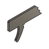
The gun's trigger is essential to its function and requires a high level of detail. To make sure all these details are preserved, the trigger was 3D printed as it is the easiest way to achieve a physical product with the necessary sharp corners. To do this, I first exported the model of the trigger as an STL file, opened it in a slicer software, (Makerbot Print in my case), and then exported it to my printer. The print settings are not important as the piece will not be undergoing any significant stress, however, to save time it was printed lying flat.
Step 3: Writing the Toolpath
The shell of the gun houses the trigger and creates the tension for the rubberbands to be fired. To make it, I used a CNC machine to cut it out of wood. The first step in this process is writing the toolpath the CNC machine follows to cut out the shell. There are many ways of doing this. The easier option is to lay out the shell pieces on a flat plane in Fusion 360 and use the "manufacture" workspace to write a toolpath automatically. However, I chose the harder option and wrote the G-Code for the toolpath by hand. This was done by drawing lines in Fusion to represent the toolpath and then using the "inspect" tool to find the X and Y coordinates of all the endpoints. The full G-Code I wrote will be attached below and can be previewed at ncviewer.com. Please take note that the RPM of the CNC machine and the feed rate of the CNC machine are based on the tools and machines I used, so you may need to change those to suit your needs. Those two variables may be altered at the beginning of the G-Code text. Type in your desired RPM directly behind the capital S, and type in your desired feed rate directly behind the capital F. You may also need to change the format of the text file from .txt to the format accepted by your machine. ex: .TAP for the Shark HD510
Attachments
Step 4: Cutting Out the Shell Halves
The exact process of cutting out the shell will vary depending on the machine you are using. In my case, I first clamped down my material to the work surface of the CNC router. I then used a touch plate to zero the Z-axis of my machine to the surface of my work material. From a top-down graphical perspective, the entirety of this operation takes place in the 1st quadrant. Thus, I set my X and Y zero to the leftmost corner of my material (where the green and red lines meet in the ncviewer preview). I exported my code onto a USB to insert it into the machine, then ran an air cut to make sure my code was working properly. Make sure the drill bit does not exceed the boundaries of your work material. Once I verified that everything was working properly, I set the Z-axis zero back to the surface of my work material, and then let the program run.
Step 5: Finishing the Halves
Once the CNC program has finished, cut the three tabs on each half to separate them from the rest of the work material. I used an oscillating saw for this. To clean up the rest of the shell, I used a wood rasp to grind the tabs down flush and then went over the whole profile with sandpaper. I also cleaned the pockets where the trigger sits with sandpaper. The holes in the shell are made to fit 1/4 in dowels, which I cut to size and glued into one half of the shell. I then placed the trigger in its pocket, placed the spring in the thin notch below the trigger pocket, and then glued and clamped the whole thing together. Once the glue dried, the gun was complete.
Step 6: Operation
Your gun is now finished! To use the gun, hook a rubber band into the half-circle notch at the front of the gun and one of the three rectangular notches at the back of the gun above the grip. As you fire, the top-most rubber band will shoot off, while the ones below it will rise one notch, allowing you to quickly fire them in succession.

Participated in the
CNC Student Design Challenge


