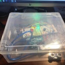
Introduction: Tic Tac Toe
Today we'll be making a Tic Tac Toe game on TinkerCad using the Arduino. We're going to be using a lot of simple components and use the code to tie them all together. The main part of this circuit that brings this all together is the code. This program has many possibilities and can be changed to however the user sees fit. This game also has the option of using RGB lights, but if anyone wants to advance on this project they'll need to connect 2 arduinos to eachother.
Supplies
- Arduino
- Breadboard (large)
- Wires
- Pushbutton
- LEDs
- Resistors (10k and 150)
- Photoresistors
Step 1: Beginning
So we're gonna begin this with a large breadboard and Arduino microcontroller.
Step 2: Adding LEDs
The next step is to add LEDs and pushbuttons to the breadboard. We aren't connecting them yet but just placing them in the board in a way so none of the wires interfere with other pushbuttons. There are a lot of components so we need to space them out like this so none touch. A large breadboard is recommended for this project.
Step 3: Digital Pins
So before we add anything else lets first connect the digital pins to the LEDs. In this project, we're going to be using all of the analog and digital pins that the Arduino has.
Step 4: PushButtons
For this step we're going to connect the power and ground to the pushbutton. In this step we're going to use 10k resistors to limit the amount of power. The 2 buttons on the right are not used to turn the LED on or off, but they are used to start a new game, and for something else we're going to see when we start the code.
Step 5: Digital and Analog Pins
In this step we're going to be connecting the buttons to the digital and analog pins. The analog pins can be used in this case because they can be used the same way digital pins are used.
Step 6: Photoresistors
In this step, we're going to be connecting the photoresistors to the LEDs. The point of this is to let different players get different levels of brightness and this allows players to differentiate themselves. In this step you see why spacing the steps apart was necessary.
Step 7: Defining Variables
In this step, we are going to start the code. The first part of this is going to be defining the different buttons and LEDs, but also another variable that is equal to 0. This variable will help us turn the LEDs on and off with the press of a button.
Step 8: Declaring Variables
In this step, we are going to be finishing the declaration of these variables and be setting the buttons as input, and the LEDs as outputs.
Step 9: Loading
This part of the code can be seen as a "loading screen". Most games usually have some start-up sequences in the beginning but this part is optional and is only done for the show. This is what the other button which was on the right could be used for. It could display the start-up sequence until a "start button" was pressed.
Step 10: LED On/Off
This step focuses on the main code of how to turn the LED on and off with the buttons. In this code, we will use the variable that equals 0 that we originally set up when defining our variables. According to this code, the LED will turn on when the button is pressed, but will turn back off when its pressed again.
Step 11: Off Button
This step codes the off button or new game button. This is used when a player has won or is done the game, and the game will be reset and can be started anew. This button is basically a reset button that restarts the loop so the game can be played over and over again.
Step 12: Enjoy Playing!
That was the end of this tutorial and I hope you have fun playing around with this circuit and code and make more and more changes to this circuit because the possibilities are endless because this is a very open program.


