

Introduction: TicTacToe V2 X or O
Hi all! I decided to repeat the project from this page https://www.instructables.com/Tic-Tac-Toe-for-Nokia-5110/, but made a few changes to the code and splash pictures, and sounds
Supplies


Used:
1) Arduino pro mini
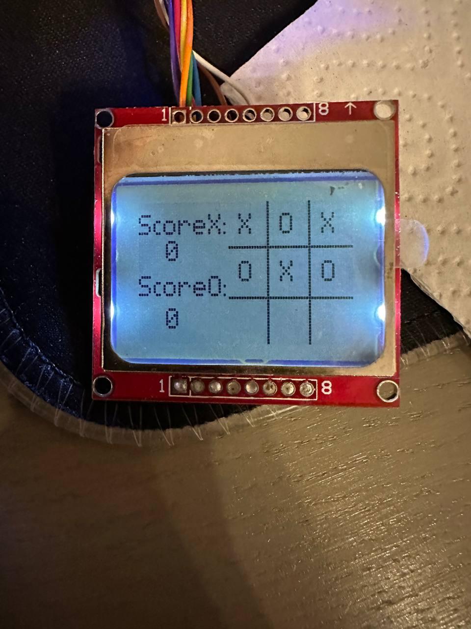
2) LCD 5110
3) push button x3
4) some resistors (look at the schema)
5) li-ion battary (i used 1000Mah)
6) programmer cp2102
7) charging board with type c for li-ion battary
8) buzzer
9) some wires
10) Straight arms :D
Step 1:
To compile project, you need to put both files in one folder, open Arduino ide, select the board type and com port, then start the compilation, there should be no errors
I changed 2 screensavers, logos when turned on and a drawing if no one won
this required paint (Windows) and a couple of sites, on one we get the required image size for the screen size 5110, on the second we get the HEX code for saving into code
https://image.online-convert.com/convert-to-bmp to 84x48
https://sparks.gogo.co.nz/pcd8554-bmp.html to HEX
I also thought that it would be convenient to see whose turn it is to make a move, so I changed the code a little, and on the screen you can see who will make a move now and added a buzzer for sound when turned on and during the game
The buzzersounds the loading of the game, each key press and the sound of the end of the game
it was like this
if(place == 1){
if(t1 >=1 ){
place++;
}else{
x=39 ;
y=4 ;
lcd.print("_",x,y);
lcd.update();
}
did this like this
if(place == 1){
if(t1 >=1 ){
place++;
}else{
x=39 ;
y=4 ;
if(turn ==1){
tn=1;
lcd.print("X",x,y);
}
if(turn ==2){
tn=2;
lcd.print("O",x,y);
}
lcd.update();
}
}
I also moved the victory counter by 10 pixels, it looked nicer this way
Step 2:


you need to solder all connections according to the diagram
arduino LCD
PIN8 -1K- SCLK;(CLK);(SCK);
PIN9 -1K-DIN;(SDIN);(MOSI);
PIN10 -1K- D/C;(DC);
PIN11 -1K- CS;(SCE) (CE);
PIN12 -1K- RST;(RESET);
VCC - VCC
GND -(a voltage divider look at the schema) GND
GND -330ohm LIGHT
Keys
arduino - keypad
pin4 (100ohm to ground) - enter (second pin to vcc)
pin3 (100ohm to ground) - left (second pin to vcc)
pin2 (100ohm to ground) - right (second pin to vcc)
I used an Arduino pro mini, there is no 3.3 volt output, I added a voltage divider to the circuit, so this connection should only be used if there is no 3.3 volt output
Step 3:


I found a suitable housing at home in which everything should fit and began to prepare it for the installation of all elements
Step 4:


After installing all the parts I checked everything, it works fine, if you have any questions, please ask
Step 5:


DONE :)


