Introduction: Tiny GPS Tracker
This project uses TinyCircuits to create a tiny GPS tracking and data logging device. This tutorial is for any skill level - no coding, programming, or soldering required! Just follow the steps below and you can have your device working in minutes.
Step 1: Materials
Step 2: Software
This project uses the Arduino IDE.
You will also need to install the most recent version of the SPIFlash library. In your Arduino IDE, open your Library Manager (under the 'Sketch' tab) and search for 'SPIFlash'. Click 'Install' to install the library to your IDE, as shown above.
Step 3: Assembling the Boards
Start with the TinyDuino on the bottom of the stack. Add the USB TinyShield, then the Flash Memory TinyShield. The GPS TinyShield goes on top.
With your Mounting Kit, add spacers between the boards on the side opposite the connector. This will make sure your stack stays rigid and prevent your connectors from coming apart if pressure is placed on that side. If you're having difficulty placing them with bare fingers, I recommend a pair of tweezers to make the job easier.
Drop the screw through the holes and placed spacers and screw in the bolt on the other side to seal the deal. Finger tightening will be just fine to hold everything in place.
Plug in your Lithium Battery and your assembly is finished!
Step 4: Uploading the Sketch

Opening the .zip file downloaded from GitHub.
Click here to download the .zip file containing the sketch. Save the 'GPS_Tracker' sketch folder as pictured above to any destination you like. Double click on 'GPS_Tracker.ino' to open the IDE.
Ensure that the connection to your TinyDuino is configured properly, turn on your TinyDuino, and hit upload. Open the Serial Monitor to ensure that your device is outputting properly.

What the Serial Monitor should display after upload is complete.
Step 5: Transporting Your Device
For optimal GPS data readings, the sensor at the end of the antenna on top of the stack should be parallel with the ground. (Note that the coiling or bending of the antenna wire will not affect your readings.) This is best achieved by carrying the stack upright in some sort of containment. Pictured above is a potential setup that I took for a test drive - I have the stack upright in an anti-static plastic bag, which could be pinned to a backpack strap or the shoulder of your coat. You can accomplish this same effect in a number of creative ways. Maybe there's a tiny box that can accompany you on your journey!
Step 6: Device Operation
When you power on your device, it will take ten seconds for the GPS module to wake and begin configuring. It usually takes a few minutes for the module to precisely determine your position, so it is recommended that you stay still with the device for a minute or two to obtain the best accuracy. Note that factors such as cloud cover, large buildings, and large land or rock masses in close proximity can affect GPS readings.

While the Summit Metroparks Gorge Trail is beautiful, the large rock structures did have an effect on my GPS data.
The sketch for the device currently specifies that a data point is taken every ten seconds. If you wish, you can change the code as shown below to adjust that.

The value I am adjusting is the number of seconds in milliseconds.
To check if your device still has power, watch to see if the LED labeled 'P13' on your TinyDuino is blinking every ten seconds (or whatever delay you set it for). This signals that the device is writing to your Flash Memory TinyShield. If you're concerned about your device losing power on long trips, you can use a standard 1 Amp charging block or battery with a micro-USB cable and connect it to the USB TinyShield to recharge the lithium battery or power the device altogether.
Before powering down your device, make sure you've left enough time for your TinyDuino to write your last data point to memory!
Step 7: Reading the Data
When you first opened the Serial Monitor to verify the operation of your TinyDuino, you saw the following dialog pop up:

The dialog that appears upon turning your device on.
We will now interact with this dialog to retrieve the data from your Flash Memory TinyShield. Send 'y' as shown below to begin read mode:

You can also hit the "enter" key to accomplish this.
We will read the data from our device by sending '1'.

The data displayed here is for example only - your data will look much different.
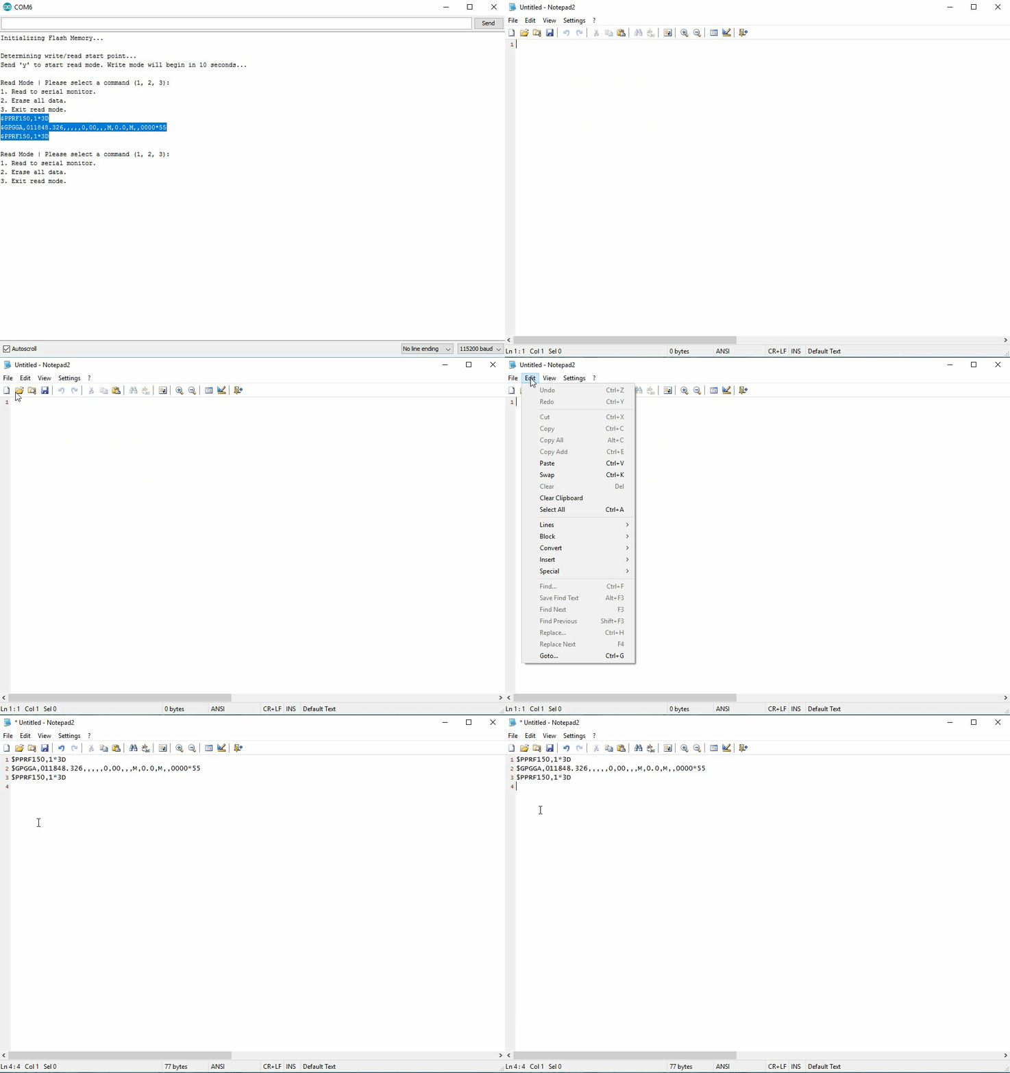
We can copy and paste the block of strings into Notepad or another plain text editor like so:

Use the shortcut CTRL + C or CMD + C to copy this data.
Save that file as a .txt file. It's ready for the next step! As for your device, if you wish to erase that trip's data from its memory, send '2' to clear all data:

Make sure you've saved all your data before taking this action!
Now we get to the best part - visualizing your GPS data!
Step 8: Converting to Google Maps

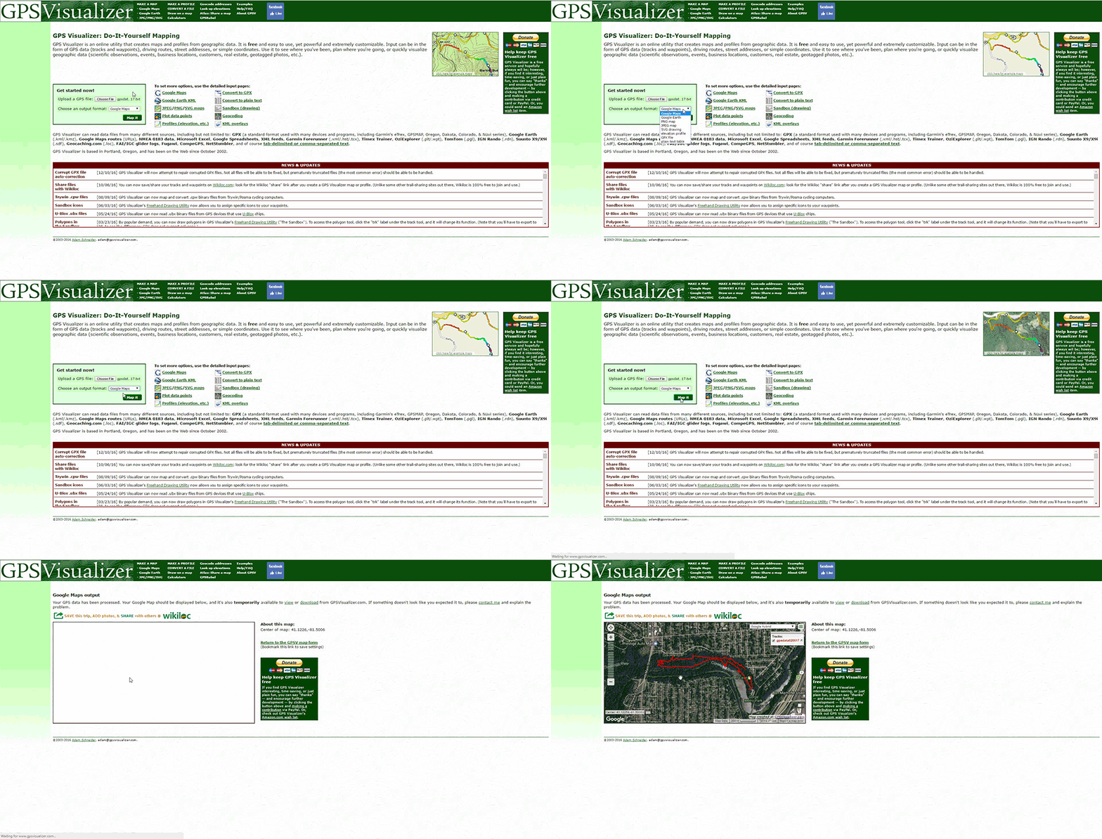
For this task, we will be using the software on GPS-Visualizer.com. Huge thanks to their team for keeping this software free of charge, and for making the mapping process simple. (If you want to help keep the software free forever, you can donate here.)
On the home page, use the 'Choose File' button in 'Get started now!' box to select the .txt file that you saved earlier. You can select any output format from the drop-down menu, but I recommend Google Maps, as it is the most dynamic and informative format. Click "Map it" and watch the magic happen!

Yes, it is that easy. There are some advanced settings that you can use to smooth out your data points that they cover in a tutorial here on their site. Otherwise, you can save your results for later, and even share them on social media!


