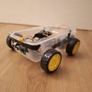
Introduction: Tuppercar
Welcome to my first Instructable.
By request of many I decided to make a simple tutorial.
First of all, this is a test setup. I just wanted to test the techniques and this came out.
This tutorial will be updated soon with more features. If you have any suggestions, dont hesitate to msg me. Below the new features/updates that are coming soon.
- A camera mount so i can move the camera (3d printing/servos)
- 3D printing a new car casing
- New battery, 12v.
- Wireless charging
Step 1: Part List
I already had all the products at home, so I quickly checked where they were for sale. Below is a list of all products that I have used.
Step 2: Building and Testing
- I started with the L298N and connecting the dc motors. I used the datasheet of the L298N found here. I connected the cables to the right connectors and powered it up (see image). For testing i used my power supply(Dps3005): 12v 1amp
- For driving i used 2x 18650 battery parallel, the output will be about 8v. This will be changed later on too 12v. But this project is a test build, so did not had time yet.
- Necessities for this step is a clean install of Raspbian on a Pi Zero W.
- Connecting the L298n to the pi.
- connected pins:
- L298n pin 10 to pi GP14
- L298n pin 3 to pi GP15
- L298n pin 5 to pi GP18
- L298n pin 11 to pi GP25
- L298n pin 6 to pi GP8
- L298n pin 9 to pi GP7
So, now we have tested the dc motors, connected the L298n with the raspberry. Guess we ready for some python code.
import RPi.GPIO as GPIO
from time import sleep

#the first dc motor pins
Motor1Enable = 14
Motor1A = 15
Motor1B = 18

#the second dc motor pins
Motor2Enable = 	25
Motor2A = 7
Motor2B = 8

Direction=1 #default is forward

GPIO.setmode(GPIO.BCM)

GPIO.setup(Motor1A,GPIO.OUT)
GPIO.setup(Motor1B,GPIO.OUT)
GPIO.setup(Motor1Enable,GPIO.OUT)
GPIO.setup(Motor2A,GPIO.OUT)
GPIO.setup(Motor2B,GPIO.OUT)
GPIO.setup(Motor2Enable,GPIO.OUT)
GPIO.output(Motor1A,GPIO.LOW)
GPIO.output(Motor1B,GPIO.LOW)
GPIO.output(Motor2A,GPIO.LOW)
GPIO.output(Motor2B,GPIO.LOW)

p1=GPIO.PWM(Motor1Enable,1000)
p1.start(25)
p2=GPIO.PWM(Motor2Enable,1000)
p2.start(25)

print("\n")
print("The default speed & direction of motor is LOW & Forward.....")
print("r-run s-stop f-forward b-backward l-low m-medium h-high e-exit")
print("\n")

while(1):
    x=raw_input()
    if x=='r':
        print("run")
        if(Direction==1):
		GPIO.output(Motor1A,GPIO.HIGH)
		GPIO.output(Motor1B,GPIO.LOW)
		GPIO.output(Motor2A,GPIO.HIGH)
		GPIO.output(Motor2B,GPIO.LOW)
		print("forward")
		x='z'
    	else:
		GPIO.output(Motor1A,GPIO.LOW)
		GPIO.output(Motor1B,GPIO.HIGH)
		GPIO.output(Motor2A,GPIO.LOW)
		GPIO.output(Motor2B,GPIO.HIGH)
		print("backward")
		x='z'
    elif x=='s':
        print("stop")
        GPIO.output(Motor1A,GPIO.LOW)
        GPIO.output(Motor1B,GPIO.LOW)
	GPIO.output(Motor2A,GPIO.LOW)
        GPIO.output(Motor2B,GPIO.LOW)
        x='z'
    elif x=='f':
        print("forward")
        GPIO.output(Motor1A,GPIO.HIGH)
        GPIO.output(Motor1B,GPIO.LOW)
	GPIO.output(Motor2A,GPIO.HIGH)
        GPIO.output(Motor2B,GPIO.LOW)
        Direction=1
        x='z'
    elif x=='b':
        print("backward")
        GPIO.output(Motor1A,GPIO.LOW)
        GPIO.output(Motor1B,GPIO.HIGH)
	GPIO.output(Motor2A,GPIO.LOW)
        GPIO.output(Motor2B,GPIO.HIGH)
        Direction=0
        x='z'
    elif x=='l':
        print("low")
        p1.ChangeDutyCycle(25)
		p2.ChangeDutyCycle(25)
        x='z'
    elif x=='m':
        print("medium")
        p1.ChangeDutyCycle(50)
		p2.ChangeDutyCycle(50)
        x='z'
    elif x=='h':
        print("high")
        p1.ChangeDutyCycle(75)
		p2.ChangeDutyCycle(75)
        x='z'
    elif x=='e':
        GPIO.cleanup()
        break

    else:
        print("<<<  wrong data  >>>")
I stole this example script some where on the internet. So no credits to me.
- Execute the script on the Raspberry like this: python motors.py
- Connect the camera to the right slot.
- Installing motion:
- sudo apt-get update && sudo apt-get upgrade
- sudo apt-get install motion
- sudo nano /etc/default/motion (Daemon to yes)
- sudo nano /etc/motion/motion.conf
- ctrl + w + stream_localhost + enter
- change value to off and close nano by ctrl + x + y + enter
- Enable camera:
- sudo raspi-config -> interfacing Options -> enable camera -> finish
- sudo modprobe bcm2835-v4l2
- sudo nano /etc/modules (and add at the end: bcm2835-v4l2 then close the file)
- sudo reboot
- Check ip by using ifconfig.
- Enter ip and port in browser like this: 10.0.0.82:8081. You need to see some live feed of the camera.
Alright, camera is working, dc motor is working, lets connect the HC-sr04 sensor. See image for the schema.
Simple python script for testing the HC-sr04 sensor:
import RPi.GPIO as GPIO
import time

#for the HC-sr04
Trigger = 4
Echo = 17

GPIO.setwarnings(False)
GPIO.setmode(GPIO.BCM)
GPIO.setup(Trigger,GPIO.OUT)
GPIO.setup(Echo,GPIO.IN)
GPIO.output(Trigger,False)

while 1:
	GPIO.output(Trigger,True)
	time.sleep(0.00001)
	GPIO.output(Trigger,False)
	while GPIO.input(Echo)==0:
	  pulse_start = time.time()
	while GPIO.input(Echo)==1:
	  pulse_end = time.time()
	pulse_duration = pulse_end - pulse_start
	distance = pulse_duration * 17150
	distance = round(distance, 2)
	print "Distance: ", distance, "cm"
	time.sleep(5)</p>
Combine all the elements
- mkdir carproject
- cd carproject
- mkdir template
- Copy the finished.py file in the carproject folder
- Copy the web.html file in the template file.(change the extension to html)
- sudo nano finished.py and edit the editable variables
- Run the project with: python finished.py
- go to the browser and enter your ip address like this: http://10.0.0.82:5010


