Introduction: UVLamp - SRO2003


Hi!
Today I will present you the realization of a UV LED lamp. My wife is a jewellery designer in polymer clay and she often uses resin to make her creations.
In principle it uses a classic resin that simply polymerizes in the open air, it works well but it is long enough to become solid (about 2 days). But recently she discovered a resin that polymerizes thanks to UV light, it is enough to expose the resinated object to a source of UV rays for a short time to make the resin solid. When she ordered the resin she hesitated to buy a lamp (it doesn't cost much...) but I stopped it right away saying : I HAVE UV LEDS ! I DON'T KNOW WHAT TO DO WITH, I CAN MAKE YOUR LAMP!!! (yes I sometimes react a little too fast when it comes to electronics... ;) )
And so here I am trying to make a lamp with what I have in my drawer bottoms...
Step 1: Obligations
- The light emitted by the lamp should be as homogeneous as possible, the lamp should illuminate the entire object that will be placed below.
- The lamp must have an adjustable countdown time of at least 1 minute 30 seconds
- The lamp should be large enough to cover objects up to 6cm in diameter but should not be too bulky.
- The lamp must be easily movable.
- The lamp must be powered by a "secure" power source (battery/adapter)
Step 2: Tools and Electronics Components


Electronics components :
- 1 Microchip PIC 16F628A
- 2 momentary switch buttons
- 2 transistors BS170
- 1 transistor 2N2222
- 2 single digit numeric display
- 1 red LED 5mm
- 17 UV LED 5mm
- 8 resistors 150 ohm
- 17 resistors 68 ohm
- 2 resistors 10 Kohm
- 1 resistor 220 ohm
- 1 buzzer
- 2 PCB boards
- wrapping wire (eg : 30 AWG)
Others components :
- 8 spacers
- some screws
- 1 pvc tube cap (100mm)
- 1 pvc pipe sleeve (100mm)
- heath shrink tubes
Tools :
- a drill
- soldering iron
- welding wire
- a programmer to inject the code into a Microchip 16F628 (e.g. PICkit 2)
I advise you to use Microchip MPLAB IDE (freeware) if you want to modify the code but you will also need the CCS Compiler (shareware). You can also use another compiler but you will need many changes in the program. But I will provide you the. HEX file so that you can inject it directly into the microcontroller.
Step 3: Schematic

Here is the schematic created with CADENCE Capture CIS Lite.
Explanation of the role of components:
- 16F628A : microcontroller that manages inputs/outputs and time for the countdown
- SW1: set timer setting button
- SW2: launch button
- FND1 and FND2 : digit numeric displays to indicate the countdown time
- U1 and U2 : power transistors for digit numeric displays (multiplexing)
- Q1 : power transistor to power on UV leds
- D2 to D18 : UV leds
- D1: status LED, light up when UV leds are power on
- LS1 : buzzer that emits a sound when the countdown is over
Attachments

Step 4: Calculations and Prototyping on Breadboard


Let's assemble the components on a breadboard according to the above schematic and program the microcontroller!
I divided the system into several parts before assembling the whole:
- a part for UV leds
- a part for display management
- a part for the management of push buttons and light/sound indicators
For each part I calculated the values of the different components and then checked their correct operation on the breadboard.
The UV leds part :
The leds are connected to the Vcc (+5V) on their anodes via the resistors and are connected to the GND on their cathodes via transistor Q1 (2N2222).
For this part it is simply necessary to calculate the base resistor needed for the transistor to have a sufficient current to saturate it correctly. I chose to supply the UV leds with a current of 20mA for each of them. There are 17 leds, so there will be a total current of 17*20mA=340mA which will cross the transistor from its collector to its emitter.
Here are the different useful values from the technical documentation to make the calculations: Betamin=30 Vcesat= 1V (approx...) Vbesat=0.6V
Knowing the value of the current on the collector of the transistor and the Betamin one we can deduce from it the minimum current to have on the base of the transistor so that it is saturated : Ibmin=Ic/Betamin Ibmin=340mA/30 Ibmin=11.33mA
We take a coefficient K=2 to be sure that the transistor is saturated:
Ibsat=Ibmin * 2
Ibsat= 22.33mA
Now let us calculate the base resistor value for the transistor:
Rb=(Vcc-Vbesat)/Ibsat
Rb=(5-0.6)/22.33mA
Rb=200 ohm
I choose a standard value from the E12 series: Rb=220 ohm
In principle I should have chosen a resistor with a normalized value equal or lower than 200 ohm but I didn't have much choice in values for the resistors anymore so I took the closest value.
The display management part:
Calculation of current limiting resistor for display segments :
Here are the different useful values from the technical documentation (digit display and BS170 transistor) to make the calculations:
Vf=2V
If=20mA
Calculation of the current limit value :
R=Vcc-Vf/If
R=5-2/20mA
R=150 ohm
I choose a standard value from the E12 series: R=150 ohm
Multiplexing management:
I chose to use the multiplexed display technique to limit the number of wires needed to control the characters on the displays.
There is a display that corresponds to the tens digit and another display that corresponds to the units digit. This technique is quite simple to implement, here is how it works (eg: to display the number 27)
1 - the microcontroller sends signals on 7 outputs corresponding to the character to be displayed for the tens digit (digit 2) 2 - the microcontroller activates the transistor which supplies the display which corresponds to the tens 3 - a delay of 2ms elapses 4 - the microcontroller deactivates the transistor which supplies the display which corresponds to the tens 5 - the microcontroller sends signals on 7 outputs corresponding to the character to be displayed for the digit of the units (digit 7) 6 - the microcontroller activates the transistor which supplies the display corresponding to the units 7 - a delay of 2ms elapses 8 - the microcontroller disables the transistor that supplies the display corresponding to the units
And this sequence repeats in loop very quickly so that the human eye does not perceive the moment when one of the displays is off.
The push buttons and light/sound indicators part:
There is very little hardware testing and even less calculation for this part.
It is calculated that the current limiting resistance for the status led:
R=Vcc-Vf/If R=5-2/20mA R= 150 ohm
I choose a standard value from the E12 series: R=150 ohm
For the push buttons I simply checked that I was able to detect the pressing thanks to the microcontroller and increment the number of presses on the displays. I also tested the buzzer activation to see if it was working properly.
Let's see how all this is handled with the program...
Step 5: The Program

The program is written in C language with MPLAB IDE and the code is compiled with the CCS C Compiler.
The code is fully commented and quite simple to understand I let you download the sources if you want to know how it works or if you want to modify it.
The only thing a little complicated is perhaps the management of the countdown with the timer of the microcontroller, I will try to explain quickly enough the principle:
A special function is called every 2ms by the microcontroller, this is the function called RTCC_isr() in the program.
This function manages the multiplexing of the display and also the management of the countdown. Every 2ms the displays are updated as explained above, and at the same time the TimeManagment function is also called every 2ms and manages the countdown value.
In the main loop of the program there is simply the management of the push buttons, it is in this function that there is the setting of the countdown value and the button to start the lighting of the UV LEDs and the countdown.
See below a zip file of the MPLAB project :
Attachments
Step 6: Soldering and Assembly


I have distributed the whole system on 2 boards: one board supports the resistances of the UV LEDs and another board that supports all the other components. I then added spacers to superimpose the cards.
The most complicated thing was to solder all the connections of the upper board, especially because of the displays that require a lot of wires, even with the multiplexing system...
I consolidated the connections and the wire with hot-melt glue and heat-shrinkable sheath to get the cleanest possible result.
I then made marks on the PVC cap in order to distribute the LEDs as well as possible to get the most uniform light possible. Then I drilled the holes with the diameter of the LEDs, on the pictures you can see that there are more LEDs in the center it is normal because the lamp will mainly be used to emit light on small objects.
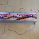
(You can see on the presentation pictures at the beginning of the project that the PVC tube is not painted like the cap, it's normal my wife wants to decorate it herself... if one day I have pictures I will add them!)
And finally I soldered a female USB connector in order to be able to power the lamp with a mobile phone charger or a external battery for example (via a male-male cable that I had at home...)
I took a lot of pictures during the realization and they are quite "talking".
Step 7: System Operation Diagram

Here is the diagram of how the system works, not the program. It's some sort of mini user manual. I have put the PDF file of the diagram as an attachment.
Attachments

Step 8: Video
Step 9: Conclusion
This is the end of this project that I would call "oportunist", indeed I made this project in order to meet an immediate need, so I did with the recovery equipment I already had but I am nevertheless quite proud of the final result, especially the rather clean aesthetic aspect that I was able to obtain.
I don't know if my writing style will be correct because I'm partly using an automatic translator in order to go faster and since I'm not English speaking natively I think some sentences will probably be weird for people writing English perfectly. So thanks to the DeepL translator for his help;)
If you have any questions or comments about this project, please let me know!


