Introduction: Uber-Light 1000

Intro:

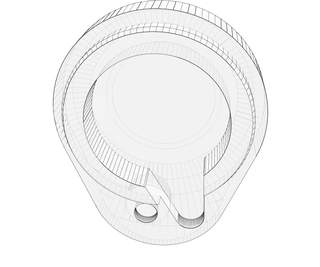
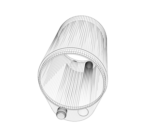
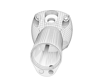
This Instructable is for a high power flashlight that uses a CREE XM-L LED and is powered by 3 D-cell batteries.  Most of the parts are fabricated using a 3D printer and due to the size/shape, it is broken down into several segments.  The wiring for this flashlight is very simple.  It composes of the 3 batteries in series, connected straight to the LED via a rocker switch.  There are no resistors in series due to the fact that there is enough resistance from the batteries (alkaline), wires, and switch.. and because the CREE XM-Ls are beastly LEDs.  Granted, this is a very inefficient way to power these LEDs for various reasons, but it does work and is really bright... battery life might just be a bit lacking... and the light output may be a bit inconsistent from beginning to end of battery life.  The middle segment of the body is sized to be the length of a D-cell battery so one can add extra segments to make it a 4+ battery light.  This will of course require different wiring/electronics... not covered in this Instructable.


Instructable Contents:
  • 1:  Tools, Materials & Parts
  • 2:  Print UL1000 Components
  • 3:  Prepare LED module
  • 4:  Assemble flashlight head (heat sink/LED module)
  • 5:  Prepare positive circuit wiring
  • 6:  Assemble flashlight body
  • 7:  Prepare/install end cap
  • 8:  Appendix A: Extra information

Step 1: Tools, Materials & Parts

Suggested Tools:
  • 3D Printer
  • Soldering Iron
  • Heat gun
  • Electric drill w/ 5/32" drill bit
  • M6-1.00 tap
  • 8-32 tap
  • 5mm Allen wrench
  • Phillips head screwdriver
  • Wire Strippers
  • Pocket knife
  • Emery cloth or sandpaper
  • Small frying pan/skillet
  • Tweezers

Suggested Materials/Parts:
  • ABS printer filament
  • Flux core wire solder
  • Solder paste
  • Heat sink compound
  • JB weld (or JB-Kwik if you are impatient like me)
  • 14" of black 20ga stranded copper wire
  • 8" of red 20ga stranded copper wire
  • 2 - 1/4" x 1" lengths heat shrink
  • 2 - female terminal ends (spade)
  • Small zip tie
  • Cree Xlamp XM-L LED (Mouser PN: 941-XMLAWT0000LT50E3)
  • LED thermal substrate (Mouser PN: 951-804936)
  • LED lens (Mouser PN: 928-FA11902T3WXM)
  • Radial heat sink (Mouser PN: 588-SA-LED-151E)
  • D-cell positive battery contact (Mouser PN: 534-5250)
  • D-cell negative battery contact (Mouser PN: 534-5251)
  • Oval rocker switch (equivalent to R13-133)
  • 1 - 8-32 x 1/2" machine screw (Phillips head)
  • 8 - M6-1.00x12mm socket head cap screws
  • 3 - D-cell batteries

Step 2: Print UL1000 Components

The first step to building the Uber-light 1000 is to print or at least start printing all the components.  I used OpenSCAD to draft the parts and attached both my .stl files and .scad files so you can easily make changes/revisions.  You can print the parts in any order you like, but I recommend following the order below so you can work on other steps while the larger components are printing.  The 3D printer I am using is a Prusa Mendel with a standard non-heated bed topped with masking tape.  I used my standard typical settings and only activate/deactivated the feature "raft"  (http://wiki.bitsfrombytes.com/index.php/Skeinforge_Raft).  For each of the components I list whether or not I used "raft" and the reasons.  Naturally, different printing configurations may require different settings.


Tools/Materials needed:
  • 3D Printer
  • Printer filament

1. Lens Bushing


Raft: No
Reason: Not needed/wasteful

2. LED Cap


Raft: No
Reason: Sometimes the raft will peel off the first couple of layers in the print.. This piece has fairly strict tolerances (don't want LED lens to be too loose or too tight).. so I leave the raft off.  Sometimes the ends curl up, but they push back flat when fastening to the heat sink.

3. Body Head Segment


Raft: Yes
Reason: It reduces warping of the bottom of the piece (where it connects to heat sink)

4. Body Mid Segment


Raft: Yes
Reason: Reduces the "mushrooming" of the bottom of the print.  Without raft, you are likely to have a ridge at the mid segment to end segment splice.

5. Body End Segment


Raft: Yes
Reason: Reduces the "mushrooming" of the bottom of the print.  Without raft, you are likely to have a ridge at the end segment to end cap splice.

6. End Cap


Raft: No
Reason: The raft is not easy to peel off of this part, resulting in an awkward layer at the very end of the light.  It is much smoother and easier without raft.

Step 3: Prepare LED Module

This step involves mounting the LED module and power wires to the thermal substrate.  There is a correct way to perform reflow soldering... and I am pretty sure the following is NOT it.  Therefore, I highly recommend doing alternate research as these components are the most fragile and most expensive parts of the flashlight.  The following does seem to work for me, so if you are feeling brave, proceed at your own risk... You could also probably buy pre-mounted LEDs... but that may require modifying the Lens Bushing/LED Cap..


Tools/Materials Needed:
  • Soldering iron
  • Wire Strippers
  • Flux cored solder
  • Soldering paste
  • Small frying pan/skillet
  • Tweezers
  • Cree Xlamp XM-L LED (Mouser PN: 941-XMLAWT0000LT50E3)
  • LED thermal substrate (Mouser PN: 951-804936)
  • 14" of black 20ga stranded copper wire
  • 8" of red 20ga stranded copper wire
  • 3 - D-cell batteries

Step 1:  Strip/tin 1/4" of one end of each wire


Step 2:  Apply solder to one of the positive and one of the negative pads on the thermal substrate.  Keep in mind that this is a heat sink, so it takes a long time heat up.  Also, the solder doesn't have to be pretty, as it will remelt when doing the reflow soldering.


Step 3:  Apply a small amount of solder paste to the LED pads on the thermal substrate.


Step 4:  Place LED on thermal substrate.  Be sure to orient the LED correctly.  It is hard to see but there is a little "+" in one of the corners of the LED.  Refer to Appendix A of this instructable for the LED datasheet.


Step 5:  Turn on stove to medium heat and place thermal pad in frying pan/skillet.  Watch closely and remove thermal pad when the solder paste melts. Depending on what types of solder/solder paste you use, you may be able to use the melting of the regular solder as an indication that the solder paste is about to melt.  


Step 6:  Solder wires to thermal pad.


Step 7:  Test assembly using 3 D-cell batteries laid out in series.  If it doesn't work... you just received a $10 education... and try again.


Step 4: Assemble Flashlight Head (heat Sink/LED Module)

In this step, you will mount LED module to the heat sink.  


Tools/Materials Needed:
  • LED module from previous step
  • Printed LED Cap
  • Printed Lens Bushing
  • M6-1.00 tap
  • 5mm Allen wrench
  • Pocket knife
  • Emery cloth or sandpaper
  • Heat sink compound
  • Small zip tie
  • 4 - M6-1.00x12mm socket head cap screws
  • LED lens (Mouser PN: 928-FA11902T3WXM)
  • Wire Strippers

Step 1:  Using M6x1/00 tap, tap the 4 large perimeter holes on the heat sink at both ends (8 taps) about 1/2" deep.


Step 2:  Using pocket knife and/or sandpaper, clean up the LED Cap and the Lens Bushing.  The idea is to have the Lens Bushing fit flush (or close to flush) inside the LED Cap.


Step 3:  Find the LED lens.  Notice that the lens will not fit on the thermal substrate due to the soldered on wires and 2 little nubs on the bottom of the lens.


Step 4:  Pick out the inner optic part of the lens and set it aside.


Step 5:  Using the wire strippers (or similar tool), cut off the interfering areas.  This will leave you with 2 half moon shaped pieces of LED lens case.  


Step 6:  Place the 2 lens case pieces on the thermal substrate around the LED using the attached adhesive.  Make sure you place the pieces such that the lens optic will fit cleanly in place.


Step 7:  Apply thermal compound to the center of one side of the heat sink.


Step 8:  Place LED module on heat sink lining up the wires with opposite center holes.


Step 9:  Place lens optic over LED in the hacked up case pieces.


Step 10:  Place Lens Bushing over LED lens.


Step 11:  Place LED Cap over Lens Bushing and install the 4 M6 mounting screws.


Step 12:  Pull the wires tight into their respective holes and secure them together with the small zip tie.


Step 5: Prepare Positive Circuit Wiring

In this step, you will prepare the positive circuit wiring to be attached to the rocker switch as well as install the battery positive contact.


Tools/Materials Needed:
  • LED/heat sink assembly from previous step
  • Printed body head segment
  • Soldering Iron
  • Flux core wire solder
  • Heat gun
  • Pocket knife
  • Emery cloth or sandpaper
  • Wire Strippers
  • JB Weld
  • 2 - 1/4" x 1" lengths heat shrink
  • 2 - female terminal ends (spade)
  • D-cell positive battery contact (Mouser PN: 534-5250)
  • 1 - D-cell battery (for fitting)

Step 1:  Using the pocket knife and sandpaper, clean up the body head segment.  The important thing is to have it so a D-cell battery will slide easily all the way to the lip inside the battery tube.


Step 2:  Cut off about 1" of red wire from the LED/heat sink assembly.  Solder one end to the positive battery contact.  Crimp or solder one of the female terminals to the other end.  Install heat shrink on the terminal end.


Step 3:  Trim the red (positive) wire from the LED/heat sink assembly so that about 1.5" is sticking out beyond the heat sink.  Solder/heat shrink the remaining female terminal to this wire.


Step 4:  Bend over the positive battery terminal tab and insert it into the battery tube resting it on the attachment bridge.  Push the D-cell battery into place and make sure it rests firmly on the battery contact.  The battery should be close, but not contact the lip on the inside of the battery tube.  Remove the battery and contact from the housing.  Apply JB Weld to the bottom of the contact and place it back on the bridge, centering the contact nipple in the battery tube.

Step 6: Assemble Flashlight Body

In this step you will assemble the body of the flashlight.  


Tools/Materials Needed:
  • LED/heat sink assembly
  • Printed body head segment
  • Printed body mid segment
  • Printed body end segment
  • Pocket knife
  • Emery cloth or sandpaper
  • 5mm Allen wrench
  • 4 - M6-1.00x12mm socket head cap screws
  • JB Weld
  • 1 - D-cell battery (for fitting)
  • Oval rocker switch (equivalent to R13-133)

Step 1:  Using pocket knife and/or sandpaper, clean up the printed pieces.  Make sure that the batteries will slide smoothly in the battery tube and that the body segment splices are nice and tight.


Step 2:  Apply JB Weld to the splice surfaces between the body head segment and body mid segment.


Step 3:  Fit the segments together and apply pressure until JB Weld sets up.  Clean out any JB Weld that finds it's way to the inside of the battery tube as well as on the outside of the splice.  Be careful not to plug the negative battery wire duct.


Step 4:  Repeat Step 3 for the body middle to body end segment splice.


Step 5:  Attach the positive battery contact to the rocker switch "supply" terminal through the rocker switch nut and mounting hole.


Step 6:  Push rocker switch into place and tighten the rocker switch mounting nut.


Step 7:  Attach the female terminal from the LED/heat sink assembly to the "load" terminal on the rocker switch.  Also feed the black negative battery wire through its duct and out the back end of the flashlight body.


Step 8:  Attach the LED/heat sink assembly to the body using the four M6 cap screws.  Be careful torquing down the screws.  If the mounting surface on the body head isn't fairly flat, you will more than likely delaminate the corners of the body head.  

Step 7: Prepare/install End Cap

This is the final construction step of the Uber-Light 1000.  In it, you will finish up the wiring and assemble/install the end cap.


Tools/Materials Needed:
  • Flashlight assembly from previous step
  • Printed end cap
  • Soldering Iron
  • Electric drill w/ 5/32" drill bit
  • 8-32 tap
  • Phillips head screwdriver
  • Wire Strippers
  • Pocket knife
  • Emery cloth or sandpaper
  • Flux core wire solder
  • JB Weld
  • D-cell negative battery contact (Mouser PN: 534-5251)
  • 1 - 8-32 x 1/2" machine screw (Phillips head)
  • 3 - D-cell batteries

Step 1:  Using the pocket knife and sandpaper, clean up the end cap and flashlight body as needed for proper fit.


Step 2:  Drill out the mounting hole on the end cap using the printed in pilot as a guide.


Step 3:  Trim the negative battery wire so that it is sticking out of the flashlight body about 1" when pulled tight.  Strip and tin about 1/2" of the wire sticking out.


Step 4:  Solder the negative battery wire to the tab of the negative battery contact, keeping it as flat as possible.


Step 5:  Tap out the end cap mounting hole in the flashlight body using an 8-32 tap.


Step 6:  Double check that the end cap fits cleanly on the housing with the negative battery contact and batteries installed.  If so, JB Weld the negative contact to the end cap.


Final Step:  Fill the Uber-Light with batteries, screw on the end cap and illuminate the world.


Step 8: Appendix A: Extra Information

This page is not really needed for the instructable, but it might have some information that could be useful or interesting.


Design considerations:
  • The middle body segment is the length of a D-cell battery so you can easily increase battery capacity.
  • On the light shown in this instructable, I used glow in the dark filament for the LED cap/lens bushing and the end cap so the flashlight can be located in the dark.
  • The egg shape of the handle not only provides room for the negative battery wire, but also provides a "directional" grip, so your thumb lines up the the rocker switch.
  • The rocker switch used has an internal light, but it won't work with 4.5 volts. This style of switch does come in a not lighted version, but I couldn't find one to buy online. I just consider the internal light to be an "on" label.
  • The lens bushing is separate from the LED cap because I wanted a positive lip to hold the lens in place.  This would have been hard to do with the 3D printer, since they don't like printing unsupported 90 degree overhangs.  They are much better at doing gradual overhangs, especially conical ones... like used in the bushing and cap.

Random Tips:
  • Use an intermediate plate for your 3D printer bed. I use a thin piece of polycarbonate (lexan). This way, it can be removed and the surface tape is easier to replace. Also, you can flex it to remove stuck on prints that are really stubborn. 
  • In OpenSCAD, if you are drafting curved surfaces, create a global variable "fn" i.e "fn = 20;". Then in all your curved shapes, set $fn = fn. i.e. "cylinder (h = 5, r = 3.25, $fn = fn);" This way, you can easily set all the the $fn values to a low number (like 20) while adjusting your object, and to a higher number (like 100) when you do your final compile and render. This will save you TONS of time during the construction of your object, since compiling and rendering an object with a high $fn takes forever and a day.

My Exact Printing Setup:  Since it is harder than you might expect to put together a compatible setup for running a Prusa Mendel, I am listing my setup below... this is more for someone who is setting up their Prusa for the first time or who is thinking of building one.
  • Linear SAE Prusa Mendel
  • Wade's Extruder w/Makergear hot end pack w/0.5mm nozzle
  • Arduino MEGA 2560 w/ RAMPS 1.4
  • Repetier Firmware Version 0.43, uploaded w/Arduino Version 0023
  • Repetier Host Software Version 0.33
  • Skeinforge 41 slicing software
  • OpenSCAD 2011.06 cad software
  • Python version 2.7.2
  • Jave JRE Version 5.0
  • Windows 7 operating system

My Prepend G-codes:
  • G28;  Homes all the axis.
  • G92 E0;  Resets the extruder steps.  Without this, the extruder will spin rapidly in reverse at the beginning of the print.

My Append G-codes:
  • M104 S0 ; turn off temperature
  • G28 X0 ; home X axis
  • G28 Y0 ; home Y axis
  • M84 ; disable motors

Make It Real Challenge
Participated in the
Make It Real Challenge