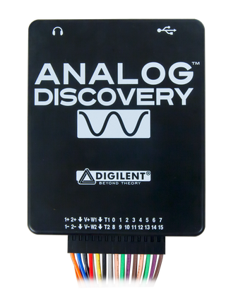
Introduction: Using the Power Supplies With the Analog Discovery 2
Bench top power supplies are one of the must-haves for any electronics hobbyist or maker. But they take up space, which for people like me with limited space, that can be a big problem. With the Analog Discovery 2 and Waveforms 2015, you can bundle multiple tools together in one small package, including an adjustable power supply.
For this Instructable you will need:

-Waveforms 2015 software

- a computer with USB port to run the software
*Most of the functionality between the Analog Discovery legacy, the AD2 and the Electronics Explorer Board is nearly identical for most of the tools. Except for the Power Supplies. The AD2 has more capability over the legacy version AD1, and the EEBoard has always had more capability than either. With that in mind, I will focus first on the AD2, then on the EEBoard, then the AD legacy.
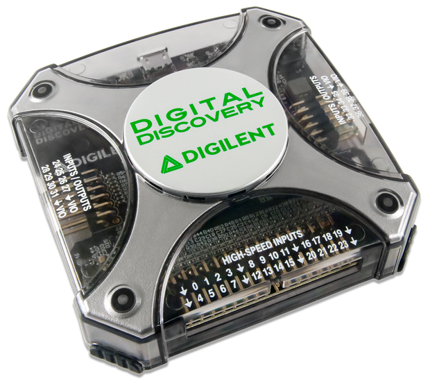
Edit: With the addition of the Digital Discovery there is a fourth version of the Power Supplies tool. This version is covered at the end of this I'ble after the AD legacy.
Step 1: Analog Discovery 2
If you want some help getting your AD2 set up and calibrated, or installing Waveforms 2015, check out this quick start I'ble collection.
Once you have your AD2 and Waveforms all set up, open the Power Supplies by clicking on the "Supplies" button.

This will open the power supplies window.

At the top you have three options: "File", "Control", and "Window".
"File" lets you Save the current power supply settings as a new project. You can then Open that project to set the power supplies to the saved setting. You can also Close the power supplies window from here.
"Control" gives access to the Run and Stop functions.
"Window" lets you view other Waveforms tools you have open, the main Waveforms screen, or the Help window.
Below that is the Master Enable button, which is the run/stop button.

Next you have the ready/on/off buttons for each power supply. If the master enable is off, you can switch between ready and off. With master enable on, you can switch between on and off.

To the right you have two drop down menus, one for the positive supply (V+) and one for the negative supply (V-). You can directly enter a value here with up to three decimal places. The accuracy of the output compared to the entered value will depend greatly on whether your AD2 is calibrated correctly. The positive supply can have any value between +500 mV and +5 V, while the negative supply can have a value anywhere between -500 mV and -5 V.

Since the Analog Discovery 2 can be powered by either the USB or a 5V auxiliary power supply, you'll see one of two notes at the bottom of the window.
The USB powered note.

The auxiliary power supply note.

Most circuits won't require more than the USB capabilities. However, in the event that you do draw more power than the AD2 can output, the program will fault and turn off all tools and outputs. This will happen if any output pin is connected directly to GND, including both power supply pins. Simply remove or change whatever is drawing a high current and try again.

Step 2: Electronics Explorer Board
The Electronics Explorer Board power supplies have many more capabilities and options than the AD2, which is why it gets its own dedicated step.

If you want some help getting your EEBoard set up and calibrated, or installing Waveforms 2015, check out this quick start I'ble collection. The calibration is similar to the AD2, and I recommend you calibrate your EEBoard before using it. You will need to have a high wattage (≈10 W) resistor between 10-50Ω and a quality voltmeter to finish the calibration.
Once you have your EEBoard and Waveforms all set up, open the Power Supplies by clicking on the "Supplies" button.

This will open the power supplies window.

At the top you have three options: "File", "Control", and "Window".
"File" lets you Save the current power supply settings as a new project. You can then Open that project to set the power supplies to the saved setting. You can Export the power supply settings, either as an image or as raw data in *.csv, *.txt, or *.tdms format. You can also Close the power supplies window from here.
"Control" gives access to the Run and Stop functions.
"Window" lets you view other Waveforms tools you have open, the main Waveforms screen, or the Help window.
Below that you have the controls for each of the four power supply types.

At the top left is Master Enable, which will turn on/off any power supply channel that has a check mark in the list below that button. Any channel that is not checked will not turn on with the Master Enable button.

To the right of the enable boxes, there are four boxes.

At the top left is the Positive Supply (VP+). You can set the voltage to any value between 0 and +9 V out to 3 decimal places. You can also set the max current limit to any value between 0 and 1.5 A out to 3 decimal places. Once VP+ is enabled and turned on, the EEBoard will send back real time voltage and current data, which will be displayed in the box below the drop down menu.
Below the Positive Supply is the Negative Supply (VP-). The parameter limitations are the same as for VP+, except negative instead of positive. Real time data will also be displayed once VP- has been enabled and turned on.
To the top right you have your Fixed Supply (Vcc). You can choose either +3.3 V or +5 V. This is really useful for powering micro-controllers/processors or FPGA chips that require a steady power supply. Real time voltage and current data is displayed below the drop down menu. You can not limit the current available on this channel.
Below the Fixed Supply are the Reference Voltages (Vref1 and Vref2). You can set these values anywhere between -10 V and +10 V. Decimal precision varies with whether you are using mV or V values. There is no real time data from the EEBoard monitoring these pins.
Next is the plot window.

At the left side you have various metrics that you can use to monitor your circuit. The Value column shows the value as of the last sample.
By clicking  you can select from a list of additional metrics to add to the watch list.

Double click on the metric you want to add, then click "Close". The new metric will appear at the bottom of the list. Note that Vmtr n is an exclusive function to the EEBoard and designates one of four built in voltmeters on the board itself. They measure voltage in reference to the internal GND plane of the EEBoard.
Clicking  lets you remove the selected metric, or clear all metrics at once. You can also press "Delete" on your keyboard to remove a highlighted metric.
With a metric highlighted,  lets you reassign a metric to that slot. You can have as many instances of the same metric as you want. You can also just double click on a metric to reassign that slot to a different metric.
 will add Maximum and Minimum columns to each metric, next to the Value column. As more samples are taken, these values will change to reflect the max or min value that has been measured by that metric.
The History box  sets the total metric history that is viewable in the plot window. You can set this value to most values between 10 s and 24 hours. If the value you enter won't work, the plot will auto correct to the closest value that will work.
 lets you change the plot update rate and how many samples are shown in the plot window. Be aware that these two values are tied to the value in the History box, and changes in one will likely affect one or both of the other two.
 will clear the plot window of all metric traces. This can be done at any time, whether the supplies are on or off. New traces will become visible as more samples begin to register.
The Plot column has a box for each metric to enable/disable that particular trace on the plot. Check the box to enable the trace.
To change the color of the trace, click on the color box in the Color column. Pick your new color from the window that opens and click "OK" to change it.
Each metric has a small gear icon  in the last column, right next to the plot window. This lets you set the vertical plot scale for that particular metric. Auto adjustment is set by default, but you can set the unit/division value and the offset value.
In the top right corner of the plot you see  . You can add or remove labels to the plot, change the background from black to white, and change the default trace width for all metrics. If you click on a metric, its trace will be slightly wider than the others and will also rise to the top layer of the plot to make it easier to see.
Lastly, just above the top right corner of the plot you'll see  . This will make the plot slide closed, widening the metric value columns on the left to allow for clearer viewing of the data. Click it again to slide the plot window back open. The plot will continue to update even if it is closed, and opening it will show the accurate history according to the rate, sample, and history settings.
Step 3: Analog Discovery Legacy
The Analog Discovery Legacy is the original version of the Analog Discovery.

Setup and calibration is the same as for the AD2, so if you want some help getting your legacy set up and calibrated, or installing Waveforms 2015, check out this quick start I'ble collection.
Once you have your Legacy and Waveforms all set up, open the Power Supplies by clicking on the "Supplies" button.

This will open the power supplies window.

At the top you have three options: "File", "Control", and "Window".
"File" lets you Save the current power supply settings as a new project. You can then Open that project to set the power supplies to the saved setting. You can also Close the power supplies window from here.
"Control" gives access to the Run and Stop functions.
"Window" lets you view other Waveforms tools you have open, the main Waveforms screen, or the Help window.
Below that is the Master Enable button, which is the run/stop button.

Next you have the ready/on/off buttons for each power supply. If the master enable is off, you can switch between ready and off. With master enable on, you can switch between on and off.

V+ is set at +5 V, while V- is set at -5 V. The accuracy of the output value will depend greatly on whether your device is calibrated correctly.
At the very bottom, there is a meter that indicates how much current the device is outputting. Keeping it low is better. If you do draw more power than the device can output, the program will fault and turn off all tools and outputs. This will happen if any output pin is connected directly to GND, including both power supply pins. Simply remove or change whatever is drawing a high current and try again.

Step 4: Digital Discovery
The Digital Discovery is the all digital version of the Analog Discovery.

Setup and calibration is the same as for the AD2, so if you want some help getting your Digital Discovery set up and calibrated, or installing Waveforms 2015, check out this quick start I'ble collection.
Once you have your DD and Waveforms all set up, open the Power Supplies by clicking on the "Supplies" button.

This will open the power supply tool window.

At the top you have three options: "File", "Control", and "Window".
"File" lets you Save the current power supply settings as a new project. You can then Open that project to set the power supplies to the saved setting. You can also Close the power supplies window from here.
"Control" gives access to the Run and Stop functions.
"Window" lets you view other Waveforms tools you have open, the main Waveforms screen, or the Help window.
Below that is the control section for the digital output voltage level.

Here you can set the output voltage level for the four VIO pins as well as any DIO (24-40) pin that is used as a digital output. Any voltage between 1.2V and 3.3V is allowed. The threshold voltage is also set here for any DIN (0-23) pin or DIO pin used as a digital input. Note that the Threshold value and slider are locked to the Voltage value and slider. Changing one will change the other. Clicking "Voltage Output" enables or disables only the VIO pins. The DIO pins 24-40 used as outputs are normally driven by the other Waveforms tools like the Logic Analyzer, Pattern Generator, Static I/O, or Digital Protocol Analyzer.

The "Digital IO Drivers" box lets you set the output current of the output pins at 2, 4, 6, 8, 12, or 16mA, or you can select "Auto". The slew rate can also be set as "Slow", "Fast", or "Quiet".

The "Digital Input weak pull" box is used to adjust the input sensitivity of the DIN (0-23) pins. Options are "Up", "Middle", or "Down".

The "Digital IO Pulls" section allows you to set default pull resistors for the 16 DIO pins (24-40). The options are "Up", "Float", or "Down". All 16 pins can be set together using the "All" buttons on the left, or each set individually using the tri-state slide switches.
Step 5: That's All There Is to It.
As you can see the Power Supplies with the Analog Discovery 2 and Waveforms 2015 software are simple and easy to use.
As always, thanks for reading. If you have questions, please ask them in the comments below, though PMs are always welcome as well. You just never know when someone else has the same question and that way we can all learn and help each other get better. Have fun building!
Also, please check out the Digilent blog where I contribute from time to time.


Participated in the
Makerspace Contest


