Introduction: Using the Real Time Clock of the Arduino 101


This is the eleventh module in the series of lessons about the Arduino 101 and it is another project using a feature uniquely available to the 101.
One of the most powerful feauture of the Arduino 101, that separates it from the Arduino Uno is that it has a real time clock (RTC). In this project we will be using it to output the current time.
Step 1: Materials and Tools

- Arduino 101
- Potentiometer
- LCD Screen
- Jumper Cables
Step 2: Circuitry
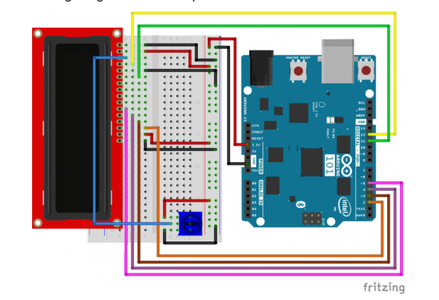


The circuitry is no different from the circuitry of the LCD module, since the RTC is internal to the Arduino 101. Unlike the Arduino Uno, we will not require a RTC timer powered separately, which makes the Arduino 101 a much more powerful tool than the Uno.
Wiring the Power from the Arduino 101 to the Breadboard
- Connect the 3.3V power from the Arduino 101 board and connect it to the red, positive power rail on the breadboard
- Connect the GND from he Arduino 101 board to the black rail on the breadboard
Connecting the LCD Screen
- It is more straightforward to follow the schematic for the LCD screen, but the following order of connections helps keep the wiring process more orderly.
- First connect the 3.3V power to the LCD screen using a red or orange jumper wire from the 3.3V rail on the breadboard
- Then connect both ground pins to the LCD screen using a black or brown jumper wire from the GND rail on the breadboard
- Then connect the pin 4 to the middle pin of the potentiometer.
- Moving on to the potentiometer, connect one of the outer pins to the red power rail, while the final potentiometer pin is connected to the ground rail of the breadboard
- Moving back to the LCD screen connect the Arduino digital signal pins to the LCD screen in consecutive order starting from pin 2. It is recommended to use similarly coloured wires as the wire diagram as it makes it more clear when troubleshooting is necessary.
Step 3: Coding

The code is slightly different from the LCD module of this series since it requires the use of the RTC and outputting the time to the display.
This uses the Curie library to use the RTC and output the time, so the code is relatively straightforward, although it requires you to initialize the current time.
//include the CurieTime Library
#include #include
//instantiate the lcd LiquidCrystal lcd(12, 11, 5, 4, 3, 2);
void setup() { //start lcd at 16 x 2 lcd.begin(16, 2);
//clear the lcd lcd.clear();
//set time
setTime(11, 43, 00, 7, 10, 2017); }
void loop() { //create a character array of 16 characters for the time char clockTime[16]; //use sprintf to create a time string of the hour, minte and seconds sprintf(clockTime, " %2d:%2d:%2d ", hour(), minute(), second());
//create a character array of 15 characters for the date char dateTime[16]; //use sprintf to create a date string from month, day and year sprintf(dateTime, " %2d/%2d/%4d ", month(), day(), year());
//set cursor to column 0, row 0 lcd.setCursor(0, 0); //print the date string over lcd lcd.print(dateTime); //set cursor to column 0, row 1 lcd.setCursor(0, 1); //print the time string over lcd lcd.print(clockTime); }
Step 4: Demo
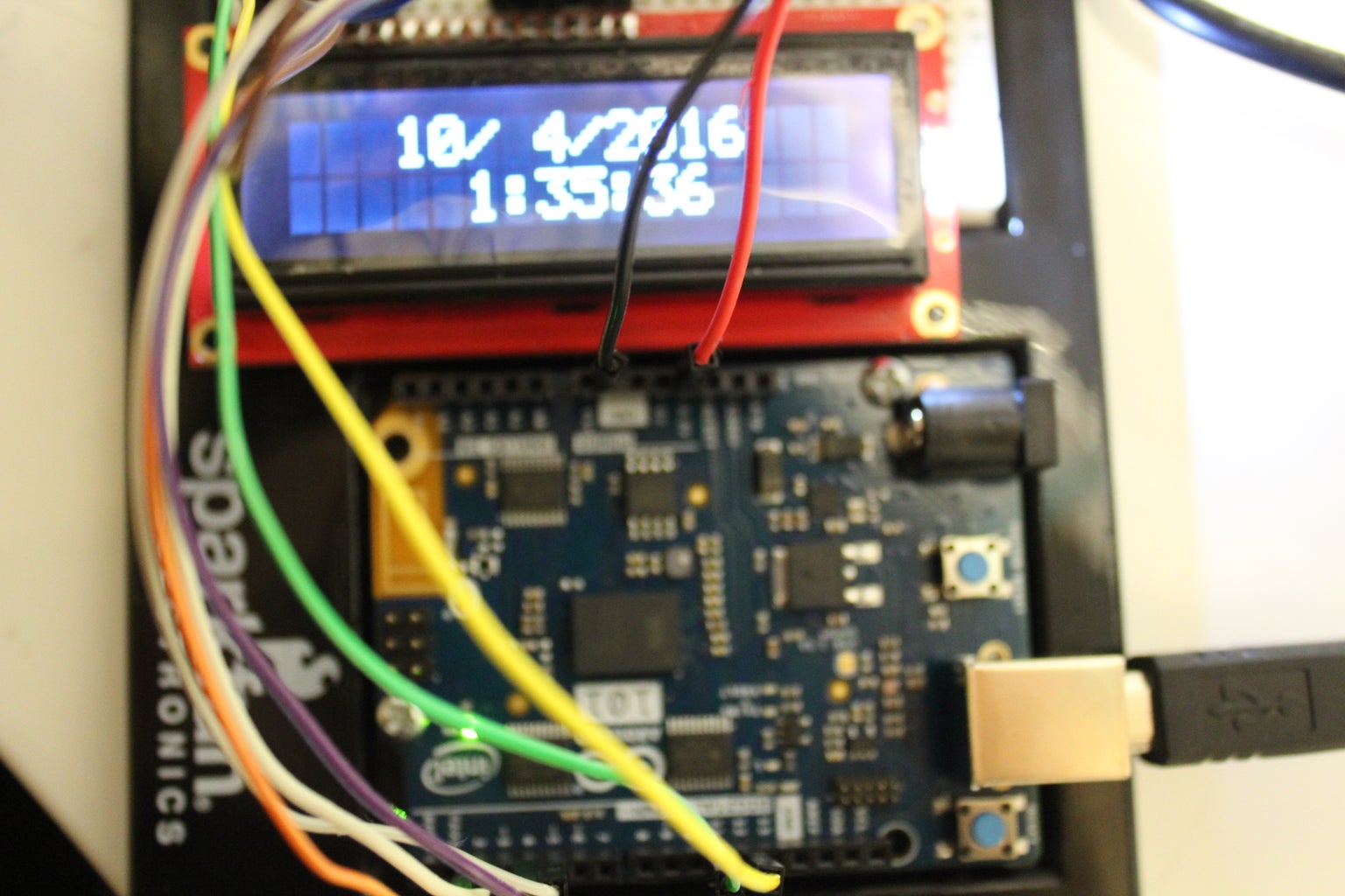
Every time the power is turned off the program resets, so it is necessary to input the new time, since unlike a CMOS, there is no separate battery keeping the RTC on at all times.

Participated in the
Makerspace Contest 2017


