

Introduction: Very Basic WIFI Chatroom Arduino Experiment With Attached ESP01 Using AT Commands


In this post, I am going to demonstrate an Arduino experiment of a very basic WIFI chatroom using an ESP01 as the WIFI module attached to an Arduino UNO / Raspberry Pi Pico / STM32 Blue Pill microcontroller board.
The sketch here is only for the "server" of the very basic WIFI chatroom -- the Arduino UNO / Raspberry Pi Pico / STM32 Blue Pill. As for the WIFI support, the attached ESP01 will use the factory ESP AT commands firmware.
This chatroom "server" is not as feature-rich as desired -- it makes the assumption that the local always-connected side is a serial monitor, and it can only accept a single remote WIFI connection to the chatroom.
Even with such restrictions, hopefully, you can still find fun with such a very basic chatroom realized using Arduino UNO.
The setting is:
- The Arduino UNO will be the chatroom "server".
- The local side of the chatroom is connected with a serial terminal to the Arduino UNO serial port.
- The Arduino UNO will use AT commands to set up a TCP server with the attached ESP01.
- The remote side can connect to the chatroom using any WIFI serial monitor, like DumbDisplay Android app
Other than Arduino UNO, other microcontroller boards like Raspberry Pi Pico or STM32 Blue Pill, etc., can be the "server", with WIFI capability provided by ESP boards that support AT commands like ESP01/8266, ESP32C3, etc.
Step 1: AT Firmware


Very likely, your ESP01 board (or other ESP boards) doesn't have the needed factory AT commands firmware. Assuming this is the case, you can re-install one as described here.
For reference, you may want to take a look at the official AT commands documents.
You will need a tool to burn the AT commands firmware. According to the Downloading Guide, you can download the tool from the page -- download the Flash Download Tools there.
For the AT commands firmware, you will also need to download the appropriate AT commands firmware from the page. Say for ESP32, follow the link ESP32 AT Bin, then the link Download ESP32 AT Released Firmware, then download the ZIP file like ESP32-WROOM-32-AT-V3.2.0.0.zip
However, for AI-Thinker ESP01 boards, instead, download the AT command firmware from the page -- https://docs.ai-thinker.com/en/esp8266/sdk
- Download the factory default AT firmware ai-thinker_esp8266_at_firmware_dout_v1.5.4.1-a_20171130.rar
- Decompress it, say with 7-Zip, and extract out the BIN file Ai-Thinker_ESP8266_DOUT_8Mbit_v1.5.4.1-a_20171130.bin.
Like uploading sketches, burning firmware to ESP01 also requires some UART to USB setup. I guess the easiest is to use an ESP01 to USB adapter board.
You burn the BIN file Ai-Thinker_ESP8266_DOUT_8Mbit_v1.5.4.1-a_20171130.bin to your AI-Thinker ESP01 board with the Flash Download Tools you download in a previous step
- Choose the firmware BIN file you downloaded in a previous step
- The firmware should be burnt to offset 0
- SPI mode should be set to DOUT
- Select the COM port your ESP01 board is attached to.
- Click Start
BTW, you can download the TTGO T-PicoC3's ESP32C3 factory firmware from T-PicoC3's GitHub repository. As a matter of fact, TTGO T-PicoC3 is the board that I initially developed the sketch for; mostly due to the fact that TTGO T-PicoC3 internally wired its Pico to its ESP32C3 basically for WIFI support with AT commands via UART.
Step 2: Try Out ESP01 AT Commands
Assuming you still have the setup for burning the firmware to ESP01. To try out its support of AT Commands, simply connect to it your favorite serial terminal
- Use baud rate 115200
- Set "line ending" to CRLF (i.e. both carriage-return and line-feed)
To test (and be sure) it is ready, enter to the local serial terminal
AT
AT

OK
Put it in "station mode". Enter
AT+CWMODE=1
AT+CWMODE=1

OK
List out the APs (access points of WIFI router) it can detect. Enter
AT+CWLAP
AT+CWLAP
+CWLAP:(3,"SOME_WIFI",-72,"ec:56:23:77:58:2c",1,60,0)
+CWLAP:(3,"SOME_OTHER_WIFI",-84,"a8:5e:45:9b:55:80",7,98,0)

OK
Connect to a specific AP of WIFI router. Enter
AT+CWJAP="SOME_WIFI","some_password_to_some_wifi"
AT+CWJAP="SOME_WIFI","some_password_to_some_wifi"
WIFI DISCONNECT
WIFI CONNECTED
WIFI GOT IP

OK
List out the IP assigned. Enter
AT+CIPSTA?
AT+CIPSTA?
+CIPSTA:ip:"192.168.0.247"
+CIPSTA:gateway:"192.168.0.1"
+CIPSTA:netmask:"255.255.255.0"

OK
Note down the IP address 192.168.0.247 shown (of cause, yours likely will be different). You will need the IP address to make connection to the server, which will be started next
Before starting TCP server, first, set it up to accept multiple connections
AT+CIPMUX=1
AT+CIPMUX=1

OK
To start it as TCP server (with port 10201), enter
AT+CIPSERVER=1,10201
AT+CIPSERVER=1,10201

OK
Note that the port of the TCP server is 10201. When making connection to the server, apart from the IP address, you will need to specify the port as well. In this example, the full connection "endpoint" will be 192.168.0.247:10201
Now, establish a WIFI connection using a WIFI serial terminal like DumbDisplay Android app, connecting to 192.168.0.247:10201.
Your local serial terminal should show
0,CONNECT
Note that the 0 of the response is the client connection "link id"
To the WIFI serial terminal, enter the line
HELLO
Your local serial terminal should show
+IPD,0,6:HELLO
Notes
- the 0 of +IPD is the client connection "link id"
- the 6 of +IPD is the length of "HELLO" + CR and LF
To your local serial terminal, enter two lines (one after another)
AT+CIPSEND=0,10
hi there
AT+CIPSEND=0,10

OK
>
Recv 10 bytes

SEND OK
Notes
- the 0 of AT+CIPSEND is the "link id" for the client connection
- the 10 of AT+CIPSEND is the number of bytes you are going to send, which is the length "hi there" + CR and LF.
- the response "Recv 10 bytes" means the AT commands firmware received 10 bytes to send to the client
The moment you send the message "hi there", your WIFI serial terminal should receive the message and display it.
Now if you drop the WIFI connection from your WIFI serial terminal, your local serial terminal should show
0,CLOSED
Note that the 0 in the response is the client connection "link id"
Step 3: Connections Between Arduino UNO and ESP01
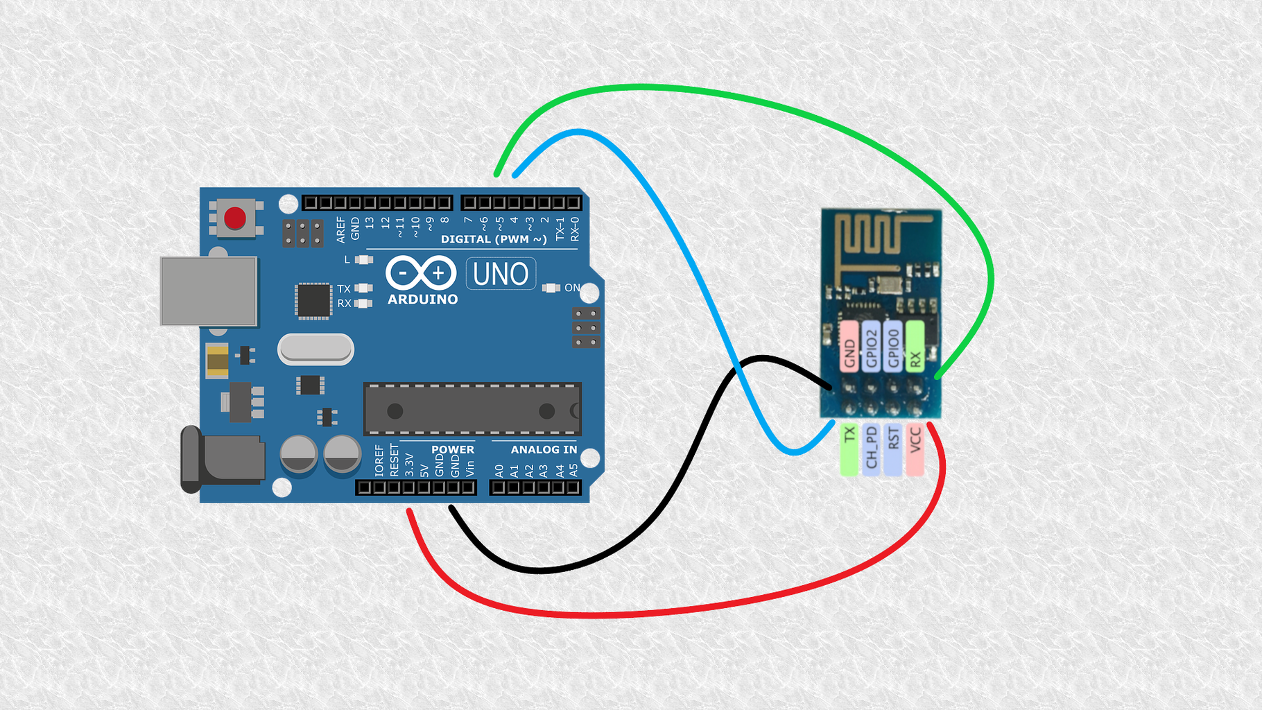
ESP01 only has a single UART, and that is the one used by the AT command firmware for UART connections. Hence
- Connect 3.3V of UNO to VCC of ESP01
- Connect GND of UNO to GND of ESP01
- Connect 4 of UNO to TX of ESP01
- Connect 5 of UNO to RX of ESP01
Depending on the actual ESP01 board used, you may need to connect 3.3V / 5V of UNO to CH_PD of ESP01, since ESP01 needs CH_PD (aka EN) to be pulled high to operate.
Step 4: Connections Between Raspberry Pi Pico and ESP01

Connections between Raspberry Pi Pico and ESP01 are similar
- Connect 3V3 of Pico to VCC of ESP01
- Connect GND of Pico to GND of ESP01
- Connect GP9 of Pico to TX of ESP01
- Connect GP8 of Pico to RX of ESP01
Again, depending on the actual ESP01 board used, you may need to connect 3V3 / VBUS of Pico to CH_PD of ESP01.
Step 5: Connections Between STM32 Blue Pill and ESP01

Connections between STM32 Blue Pill and ESP01 are similar
- Connect 3.3 of STM32 to VCC of ESP01
- Connect G of STM32 to GND of ESP01
- Connect A3 of STM32 to TX of ESP01
- Connect A2 of STM32 to RX of ESP01
Again, depending on the actual ESP01 board used, you may need to connect 3.3 to CH_PD (EN) of ESP01.
Step 6: Sketch to Try Out AT Commands
With such connections between Arduino UNO / Raspberry Pi Pico / STM32 Blue Pill and ESP01, you can try out AT commands to the ESP01 using a serial terminal connected to Arduino UNO / Raspberry Pi Pico / STM32 Blue Pill.
#include <Arduino.h>

#if defined(ARDUINO_AVR_UNO)
  // Arduino UNO
  // . 4 => TX; 5 => RX
  #include "SoftwareSerial.h"
  SoftwareSerial ss(4, 5);
  #define ESP_SERIAL ss
#elif defined(ARDUINO_ARCH_RP2040)
  // Raspberry Pi Pico
  // . TX: 8 ==> ESP01 RX (GPIO3) ; RX: 9 ==> ESP01 TX (GPIO1)
  UART Serial2(8, 9, 0, 0);
  #define ESP_SERIAL Serial2
#elif defined(ARDUINO_ARCH_STM32)
  // STM32
  // . STM32 PA3 (RX2) => ESP01 TX
  // . STM32 PA2 (TX2) => ESP01 RX
  HardwareSerial Serial2(PA3, PA2);
  #define ESP_SERIAL Serial2
#else
  #error "Unsupported board"
#endif

void setup() {
  Serial.begin(115200);
  ESP_SERIAL.begin(115200);
}

void loop() {
  if (ESP_SERIAL.available()) {
    Serial.write(ESP_SERIAL.read());
  }
  if (Serial.available()) {
    ESP_SERIAL.write(Serial.read());
  }
}
Notes
- In any case, AT commands firmware will be using baud rate of 115200, and the Arduino UNO / Raspberry Pi Pico STM32 Blue Pill will also be using baud rate 115200 for connecting the serial terminal.
- The serial terminal's "line end" should be set to CRLF, since CRLF is what expected by the AT commands firmware.
You can try out AT commands as described in a previous section.
Step 7: Sketch for the Very Basic WIFI Chatroom
You can down the sketch of the very basic WIFI chatroom here🔗 -- espatchat.ino. Since the sketch also depends on some helper routines, please also download it here🔗 -- _loespat.h. Put both files in the same directory espatchat.
The sketch should build for the above-mentioned chatroom "server" microcontroller boards -- Arduino UNO / Raspberry Pi Pico / STM32 Blue Pill.
Nevertheless, a little bit of modification of the sketch is needed from you -- define your WIFI router SSID and password, like
#define WIFI_SSID        "<wifi-ssid>"
#define WIFI_PASSWORD    "<wifi-password>"
#define WIFI_PORT        10201
By default, the WIFI port for connecting to the chatroom is 10201. You can change it to whatever you want.
In any case, communication with ESP01 is via a "serial object", which is defined by the macro ESP_SERIAL
#if defined(ARDUINO_AVR_UNO)
  // Arduino UNO
  // . 4 => TX; 5 => RX
  #include "SoftwareSerial.h"
  SoftwareSerial SS(4, 5);
  #define ESP_SERIAL SS
#elif defined(ARDUINO_ARCH_RP2040)
  // Raspberry Pi Pico
  // . TX: 8 ==> ESP01 RX (GPIO3) ; RX: 9 ==> ESP01 TX (GPIO1)
  UART Serial2(8, 9, 0, 0);
  #define ESP_SERIAL Serial2
#elif defined(ARDUINO_ARCH_STM32)
  // STM32
  // . STM32 PA3 (RX2) => ESP01 TX
  // . STM32 PA2 (TX2) => ESP01 RX
  HardwareSerial Serial2(PA3, PA2);
  #define ESP_SERIAL Serial2
#else
  #error "Unsupported board"
#endif
Notice that for Arduino UNO, SoftwareSerial (SS) is used. For Raspberry Pi Pico, UART (Serial2) is used. For STM32 Blue Pill, HardwareSerial (Serial2) is used.
It should be stressed that for Arduino UNO, the baud rate used between Arduino UNO and ESP01 is not the default 115200, rather, 14400 is used
void setup() {
  Serial.begin(SERIAL_BAUD_RATE);
  ESP_SERIAL.begin(115200);
  ...
#if defined(ARDUINO_AVR_UNO)
  // adjust the baud rate, temporarily, between Arduino UNO and ESP01
  LOEspAt::SetBaudRate(14400);
  ESP_SERIAL.begin(14400);
#endif
  ...
}
If the baud rate is not lowered, it appears that "software serial" cannot keep up.
Note that this baud rate change does not affect the serial terminal baud rate, and hence you will not notice it.
Step 8: Build, Upload, and Try
After uploading the sketch to the chatroom "server" microcontroller board, connect it to a serial terminal.
Note that the serial terminal (likely your computer) will provide power to the "server" microcontroller board, and it in turn provides power to the attached ESP01 board.
Set the baud rate of the serial terminal to 115200, and set "line end" to LF. You should see lines like
*** initializing ***
*** ready ***
*** Connected to AP with IP 192.168.0.247
END POINT: 192.168.0.247:10201
END POINT: 192.168.0.247:10201
END POINT: 192.168.0.247:10201
END POINT: 192.168.0.247:10201
Now, establish a WIFI connection using a WIFI serial terminal like DumbDisplay Android app, connecting to 192.168.0.247:10201.
*** Client connected with 'link id' 0
And the chatroom will send to the WIFI client the message "<hi there>". And if the connection is ok, you should see such a message.
Reply with the message "How are you?"
The chatroom should receive such a message, and show to the serial terminal
<<< How are you?
It is now turn for your local client to reply. Enter the line "I am fine!" to your serial terminal
>>> I am fine!
Your WIFI serial terminal should see the message "I am fine!"
If you disconnect your WIFI connection now, you should see
XXX client disconnected
END POINT: 192.168.0.247:10201
END POINT: 192.168.0.247:10201
END POINT: 192.168.0.247:10201
And the chatroom is waiting for another WIFI client connection.
Step 9: Enjoy!
Even restricted, hope that you can have fun with such a basic chatroom. Enjoy!
Peace be with you! May God bless you! Jesus loves you!


