Introduction: WiFi DCC Command Station for Model Railway


Updated 5 April 2021: new sketch and mod to circuit components.
New sketch: command_station_wifi_dcc3_LMD18200_v4.ino
Brand new DCC system using WiFi to communicate instructions
3 users of mobile phone/tablet throttles may be used on a layout ideal for both home and club model railways
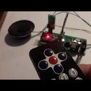
A very simple electronic circuit provides the DCC signal and power for the track, however the App does the real work !
The computer on your phone is utilised to the full by constructing the codes required to form each packet of instructions, thus simplifying the job of the micro-controller !
App available at £8.49 on Play Store 'Locomotive DCC 3 WiFi'
- this App must be installed in devices with Android 7 upwards.
The easiest ever NMRA compliant DCC Command station !! Look at the list of features below !!
Suitable for standard NMRA compatible decoders e.g. Bachmann, Lenz, Atlas, Hornby, etc
Features include:
Up to 3 users on Android phones or tablets (useful for club members)
4 Digit loco addressingProgramme on the main (PoM)
Consist control
Control of 1 to 50 locosDrives up to 12 OO/HO locomotives
Short circuit protected
Automatic overload cut-out
Lights and direction
Functions 1 to 28
Turnout / points / accessories up to 255 pairs of outputs
Custom naming of your locos
Change any function to momentary on/off switches
App has editable titles, visibility and momentary options on 28 function buttons
App has 4 on-screen speed bars for control of 4 locos at a time
Add max speed for each loco
Choose a DC power source to suit scale used (Z/N/OO/HO/O) 14v to 16v
Parts list:
1 off ESP32 S Development Board 2.4GHz WiFi+Bluetooth Antenna CP2102 Module
Note: see pin out diagram for correct device configuration for this PCB design
1 off Arduino Pro Mini Atmega328P 5V/16M
1 off LMD18200T H-bridge IC
1 off 0.1 ohm 2W Metal Film Resistor (11.5 mm x 4.5 mm)
7 off Capacitor 0.1uf
Note: the 10k resistor next to the 4.7k is not required for WiFi version
1 off 470 ohm (in place of 10k next to 0.1 ohm resistor
1 off 2k8Ω Resistor (this can be a 2.2k or 2.7k or 2.8k)
2 off 180Ω Resistors
1 off Capacitor 10uf 25v;
1 off Capacitor 220uf 16v;
1 Phoenix Contact MKDS 1/ 2-3,5 2 Way Screw PCB Terminal Block 13.5A 200V 3.5mm
1 4.7kΩ Resistor
1 L7805 CV Positive Voltage Regulator IC with 1 Heatsink TO 220 style for L7805
Note: this 5v regulator will run hot, unless sufficient heat sink is used
It may be required to mount this externally from the PCB with wire connections
2 off 15 pin Female Header Edge Pins Strip 0.1" 2.54mm
2 off 12 pin Female Header Edge Pins Strip 0.1" 2.54mm
1 off 6 pin 2.54mm PCB Universal Screw Terminal Block
1 off Zener Diode 4.7V 0.5 watt or 3.6v 0.5 watt
Wire
Power `supply:
Do NOT use a DC train controller as these do not provide a true DC voltage.
15V 2 Amp version with a 2.1 x 5.5 mm plug, search for eBay item # 401871382681
Step 1: Insight Into ESP32 Features & Using It With Arduino IDE

Few years back, ESP8266 took the embedded IoT world by storm. For less than $3, you could get a programmable, WiFi-enabled micro-controller being able to monitor and control things from anywhere in the world. Now Espressif (The semiconductor company behind the ESP8266) has released a perfect super-charged upgrade: the ESP32. Being successor to ESP8266; not only does it have a WiFi support, but it also features Bluetooth 4.0 (BLE/Bluetooth Smart) – perfect for just about any IoT project.
The ESP32 Integrates 802.11b/g/n HT40 Wi-Fi transceiver, so it can not only connect to a WiFi network and interact with the Internet, but it can also set up a network of its own, allowing other devices to connect directly to it. The ESP32 supports WiFi Direct as well, which is a good option for peer-to-peer connection without the need of an access point. The WiFi Direct is easier to setup and the data transfer speeds are much better than Bluetooth.
The chip also has dual mode Bluetooth capabilities, meaning it supports both Bluetooth 4.0 (BLE/Bluetooth Smart) and Bluetooth Classic (BT), making it even more versatile.
In this project, I only use the WiFi capability to create a local server for the DCC command station to communicate with an Android App.
In theory, it is possible to only use the ESP module, however the clock generation code required is completely different from the AVR clock code use in the Arduino Pro Mini. I leave this task to another reader out there!
The connections between ESP32 and Arduino are really simple - see circuit diagram. The RX,TX from Pro Mini connect to the Rx2,Tx2 of the ESP device. Note the use of resistors to step down the signal level to the ESP32 as it can only use 3.3v levels.
Step 2: Circuit Diagram and PCB
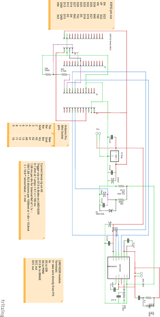


The Arduino circuit is the same as that used in the Bluetooth version. I have added sockets to mount the ESP32 in place of the BT module. This PCB is now available for sale on eBay here.
The Arduino must be a Pro Mini ATmega 328 16MHz 5v version
The ESP32 acts as a WiFi server, receiving data from the WiFi_DCC App and transmitting this to the Arduino via TX2 pin. Any data going back to the App will be sent via the RX2 pin.
A current sense resistor 0.1 ohm detects overload and short circuit conditions which then sets down the system until a reset signal is received.
The LMD18200T h-bridge converts the DCC packet into a AC waveform that supplies the track with power and data.
Note: The 5 volt regulator in a TO-220 package gets hot when powering the ESP32 module (up to 200 mA) therefore a heatsink must be used.
Step 3: ESP32 Node MCU Sketch
Updated 30/11/2020 - please use new sketch attached 'DCC_WiFi_v3.ino'
Updated 17/7/2020 - please use new sketch attached 'DCC_WiFi_v2.ino'
This sketch sets up your local server and receives updates from the App on your android device.
The communication is 2-way to allow data on current drawn by the system to be reported back to the App.
Go to GitHub link to obtain required library files here.
ESP32S must be programmed via the Arduino IDE.
Go to Tools, Board, and select Node32S or NodeMCU-32S from list.
Go to Tools, Port and select /dev/cu.SLAB_USBtoUART
That is the option on my Apple MacBook Air - something similar on PC I would imagine.
The Arduino sketch 'DCC_WiFi_v1.ino' requires these library files :
// for App 'LocoMotive WiFi Controller'
// creates a WiFi access point and provides a web server on it
#include "WiFi.h"
#include "WiFiClient.h"
#include "WiFiAP.h"
const char *ssid = "DCC_WiFi"; // must be matched in Android device settings
const char *password = "123456789"; // must be entered when above ssid is selected
WiFiServer server(80);
Attachments

Step 4: Arduino Pro Mini Sketch
Updated 5/4/2021 - please use new sketch attached 'command_station_wifi_dcc3_LMD18200_v4.ino'
Updated 24/3/2021 - please use new sketch attached 'command_station_wifi_dcc3_LMD18200_v3.ino'
To load a sketch on to the Arduino Pro Mini you need a USB- TTL adapter such as the CH340 available on eBay or here on Hobby Components website :
https://hobbycomponents.com/usb-interface/586-ch34...
Step 5: WiFi_DCC App

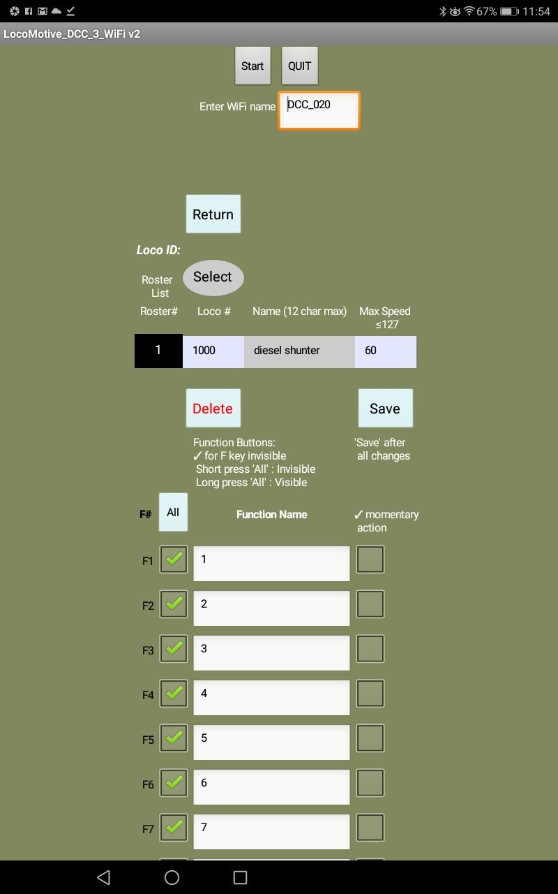


The App is available on Google Play Store here 'LocoMotive DCC 3 WiFi'.
The App may be loaded onto more than one Android device to provide multiple DCC throttles.
Note: App works well on Android 7, however on Android 9 upwards you must switch OFF 'mobile data' in the phone settings
You may also have to switch ON GPS in the Location settings of your device.
Also, you must click the Get WiFi button a couple of times to connect effectively.
The instructions for the App Locomotive DCC 3 WiFi is attached below.


