

Introduction: Wood Lathe Router Jig (Horizontal Milling)


Add horizontal embellishments or create polygon blanks using your wood lathe indexing feature and this jig!
This project will mount a small trim router to this sled and slide along the lathe bed (X axis), includes minor adjustments for Y & Z axes (yes, the plural of axis - had to look that one up!). I have also created a YouTube video to show how it is constructed and used safety to supplement this Instructable’s Guide. This is my Mark III (Mark I was the prototype and Mark II was too complex and not usable). Possible Mark IV to be discussed in Lessons Learned (Step 4, below).
https://youtu.be/kxV6o-SSdqI (posting at 1730 on June 29, 2023)
CAUTION: This includes the use of power tools (lathe and trim router). Ensure you are familiar with all precautions and warnings, and have appropriate personal protective equipment, for your tools prior to using this jig. During use ensure the lathe bed is clean to prevent friction with the base of the Sled and Rail Guide.
Supplies
Provided:
o Wood Lathe Router Jig Cut Sheet
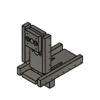
o Wood Lathe Router Jig Orthographic Sketch
Tools:
o Wood Lathe (the provided cut sheet is based on my Jet JWL-1221VS, the Rail Guide dimensions may need to be adjusted to your lathe)
o Trim Router (battery operated recommended, but not necessary - the provided cut sheet is based on my Ryobi 18V ONE+ Palm Router [P601], the Mount and some other dimensions may need to be adjusted for your router)
o Router Collet Extension (see Lessons Learned - Step 4, below)
o Saw, table saw recommended but other tools (including hand tools) could be used
o Router, drill, drill press, or hand tools for mortising (I used an upcut spiral bit with the router first, but found a Forster bit on the drill press easier to hog out the material first
o Hand drill with bits
o Screwdriver (appropriate type for screws…)
o Wrench/pliers of some sort
Materials:
o Wood glue
o Wood screws (I used #6 x 1”)
o Machine screws (based on your trim router for mounting)
o Hardwood (I used a 1 inch x 4 inch x 4 foot - nominal 3/4 inch x 3-1/2 inch x 4 foot - red oak board, more or less may be needed based on your setup)
o Hardwood (cutoffs can be used) or UHMW (dimension for the Rail Guide)
o Two 3/8-16 1-1/2 inch carriage bolts
o Two 3/8-16 2-1/2 inch carriage bolts
o Four 3/8-16 nuts, wing nuts, or knobs
o Four 5/16 inch flat washers (these should fit the 3/8 inch bolts)

Step 1:
Step 1: Cut Sheet
Using the Cut Sheet, cut out all parts. I cross-cut the board down to the 3-1/2 inch dimension for the full length, then cross-cut the remainder down to the 1-1/2 inch dimension for the full length. From there, I rip-cut each part down to the final dimensions. The Rail Guide can be cut from one larger piece or from glued up pieces.
I found that a straight grained red oak plank works best. I felt even the higher-grade plywood was too soft and pliable for the structure needed for this jig.
Some dimensions may need to be modified for your lathe and trim router.
Cut list:
o One Upright
o Two Upright Braces
o One Mount
o One Sled
o Two Sled Braces
o One Rail Guide
Step 2:
Step 2: Prepping Parts (referencing the Cut Sheet)
Mortise channels on the Upright and Sled. The channels for attaching the Upright to the Mount and the Sled to the Rail Guide are 3/8” diameter and the Upright also has a 1” diameter channel for the router bit to extend through.
For the Sled, cut a dado 3/4” wide by 1/4” deep to hold the base of the Upright (this provides additional structure support when glued and screwed in later).
The Mount and the Rail Guide will have two 3/8” holes, each with a 1” countersink to hold carriage bolts for attaching to the Upright and Sled, respectively.
The Mount will also have a 1” diameter hole in the center for the router bit to extend through and four countersunk holes aligned and sized for the trim router to be used (the countersunk mounting sides will be on the opposite side from the countersunk holes for the carriage bolts).
Drill pilot holes in all four braces and in the dado on the Sled for installing the wood screws.
The Sled Braces will have one pilot hole countersunk to allow the Sled Brace to be affixed to the respective Upright Brace.
The Sled Braces will be mounted with the base flush with the base of the Sled.
The Upright Braces will be mounted with the base flush to the lathe side of the Upright (this will provide additional support for the router and allow a channel for the mount to slide in).
Step 3:


Step 3: Fitting Parts
I recommend fitting all pieces first, then dismantling the jig and gluing the appropriate joints to provide the structural strength needed.
Attach the Sled Braces on the sides of the Sled with glue and screws.
Ensure the base of the Sled Braces are flush with the base of the Sled and the countersink hole for attaching the Sled Braces to the Upright Braces on the base side.
Attach the Upright Braces to the Upright and to the Sled Braces with glue and screws. Ensure the lathe side of the Upright Braces are flush with the lathe side of the Upright. This will help provide additional support against the trim router and a channel for the Mount to slide in.
Attach the Upright to the Sled through the dado and join with glue and screws.
The Mount will be fit to the Upright in the channel between then Upright Braces with two 1-1/2 inch carriage bolts. I recommend waxing to prevent accidently gluing to the Upright and Braces. Ensure the countersink holes for the trim router mounting are on the lathe side and the countersink holes for the Upright bolts are on the user side. The carriage bolt heads will be in the countersinks on the Mount, with a flat washer and a nut, wing nut, or knob on the lathe side of the Upright. Tighten the nut, wing nut, or knob to seat the square base of the carriage bolt in the Mount countersink.
The Rail Guide will be fit to the base of the Sled with two 2-1/2 inch carriage bolts. I recommend waxing to prevent accidently gluing to the Sled and Braces. Ensure the countersink holes are at the base of the Rail Guide. The carriage bolt heads will be in the countersinks on the Rail Guide, with a flat washer and a nut, wing nut, or knob on the top side of the Sled. Tighten the nut, wing nut, or knob to seat the square base of the carriage bolt in the Rail Guide countersink.
Once the glue has completed curing, remove the Mount and attach the trim router through the mounting holes, ensuring the mounting screws are fully in each countersink so they will not interfere with the attachment to the Upright. Install a router collet extension and router bit with a fine point and reattach the Mount to the Upright. Center the mount to the lathe centerline axis (referencing against a center), tighten the Mount to the Upright, and mark this position on the Upright/Upright Braces.
Finish the rig as desired. The base of the Sled and the Rail Guide should include a finish that allows the smooth movement on the lathe bed. The Mount and Rail Guide positions can be adjusted to change the position of the cut or to allow more space for larger pieces.
Step 4:
Step 4: Lessons Learned
The addition of the Mount to allow Y-axis movement requires using a Router Collet Extension. This causes a bit more flex than I like - so take multiple, shallow passes. The Mark I had a fixed Y-axis and did not have this issue. I will likely continue to use the Mark I jig when Y-axis adjustments off the centerline are not needed.
Mark IV may use a router with a 1/2 collet (if I can find one small enough) to allow using a more stable collet extension. I may also cut back my 1/4 Router Collet Extension so it will sit flush with the router collet nut for stability - this may lose too much of the extension though. I am also considering using a pivot point on the sled, similar to a sphere jig, to allow adding flares and insets.
Try to add a counterweight on the far side of the jig - this will help with control. I used the battery for my router, with a homemade extension cord. I also maintain downward pressure on the sled with my working hand.
Keep your lathe bed clear. This will help prevent the jig from binding or not having a full travel path.
Don’t get overzealous with the bits you chose. The larger and/or more complex bits require more power and control and tend to grab as well. Simple patterns alone can greatly help accentuate a piece. High quality, sharp bits would help greatly as well. There is a place for lower quality bits and this jig is not it!


