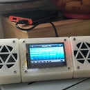
Introduction: Wood and 3D Printed ESP32 Webradio
In this Instructable I am going to show you how to make a webradio/"SDcard MP3" player using an ESP32 and how to make a 3D printed housing with wooden accents for it.
My mother recently moved into a new house and wanted to replace the old boombox that used to play music in the bathroom, so I designed this radio to specifically fit onto a shelf in the new bathroom. It's not a HiFi system, but its good enough to sing along to some tunes in the shower.
The sofware is from an awesome GitHub Project by Ed Smallenburg. It's written for the Arduino IDE and is very well documented, so even if you don't know much about the ESP32, or how to program it, you shouldn't have any problems getting this to work: https://github.com/Edzelf/ESP32-Radio
You will need:
- An ESP32 Dev Kit
- A VS1053B MP3 Decoder Board
- A 1.8" TFT LCD Display with SD Card slot
- A Class D Stereo Audio Amplifier
- A 3W 4Ohm Stereo Speakers
- A Micro-B USB Breakout Board
- Flexible Jumper Wires
- A Push button (ON-OFF)
- M3 Machine Screws and Nuts
- Wood Veneer (Walnut contrasts nicely with black PLA)
- Any FFF 3D Printer or Printservice such as 3D Hubs
- Utiliy Knife
- Wood Varnish
- CA Glue
- Hot Glue
Step 1: Program the ESP32
Let's start by loading the ESP32 up with the software an configure which pins we want to use. Download the GitHub repository as a zip file or clone it to your computer from here. Unzip the archive and open the main .ino file in the Arduino IDE. Connect the ESP32 to your computer via a USB cable.
If you've never used an ESP32 with the Arduino IDE, add the following URL to the list of "Alternative Board Manager URL's" in the prefences of the IDE: https://dl.espressif.com/dl/package_esp32_index.js. Next, go to Tools>Board>Boardmanager... ,search for "ESP32" and install the new boardmanager. Once it is installed, you can choose the "ESP32 Dev Module" from the list of boards.
You may need to install some additional libraries, but if so, the IDE will notify you about this when first attempting to upload the code to the board. The Arduino website explains how to add libraries very nicely.
After uploading the code, the ESP will create a WiFi AP from which you can reach a web interface where you can change the configuration of the webradio. The details may change in future, as the project develops, so I will link to the PDF documentation instead of repeating what has already be written.
In the configuration window you can enter one or multiple sets of WiFi credentials, change some of the pins used on the ESP as well as add and remove up to 100 radio station presets.
Step 2: Print the Housing
I designed the housing for the webradio in Fusion360 and printed it in black PLA on my 3D Printer. The design consists of a main body, with a front and rear plate which snap-fit into place. All parts print with minimal support. I included the .f3d files as well as the .stl files, so feel free to change the housing however you like. You can also find the CAD files on my thingiverse page.
There are also some speaker covers which you can print. I meant to cover them with acoustic cloth and have them attach to the housing with magnets, so that they could be removed. Unfortunately the magnet/screw combo I used didn't work and I only thought about magnetising the screws after it was too late (see next step), so I didn't use them.
The front plate holds the LCD, roary encoder and both speakers and should be printed face down. The rear plate has standoffs for the ESP32 and a micro USB breakout board. The main body has a hole for a 12 mm LED latching push button that can act as a power button.
I also designed a knurled knob for the rotary encoder as I couldn't find any online, that were both within my budget and looked nice enough. I was suprised by how well it turned and didn't expect my Anet A8 to be able to handle the miniscule knurling. This also prints without support.
Step 3: Applying the Wood Veneer
Although you could leave the housing as is, I wanted to add some wood accents to it. If you print the front and rear plate face down, you no only use the least support, but the surface is even enough to glue some veneer to it. Carefully cut a piece of verneer to the rough shape of the rear plate. Apply a bead of CA glue around the edge of the print and some to the middle as well (the liquid kind is better suited to this that the gel type). Turn the print upside down and slowly lower it onto the veneer, then press down firmly. Do this on a flat surface and wipe away any excess glue that might ooze from the sides. After a few seconds, the glue should have cured enough for you to lift the plate with the veneer on it back up.
Next you can trim the excess veneer with a utility knife or razor blade. Take your time doing this, as the veneer will cut easily with the grain, but is quite brittle when cutting across it. Get as close to the print as you like with the blade, then sand the veneer edges flush with some sandpaper. I was in a hurry, so I trimmed all the way up to the print with a blade and snapped some of the veneer off of the rear plate. I glued it back in place and you can hardly notice it, but it could have been avoided if I haded spent some more time on it.
The front plate is a little bit trickier as there are more openings to cut out and trim, but the procedure is basically the same. I didn't want the screws that hold the Speakers to visible later on, so I screwed them into place using M3 machine screws and corresponding nuts before applying the veneer. This makes cutting out the speaker holes a bit more tedious, as you have to careful not to cut into the speaker membrane. If you don't feel comfortable doing this, just stick the veneer on first and cut out the screw holes afterward.
If you wanted to you could try to stain the veneer, but I'm not sure how that would affect the CA glue underneath. I decided to go with a wax based varnish which will only protect the wood to a certain degree, but definitely made the grain pop more, which looks very nice.
Step 4: Hook Up the Electronics
The electronics are relatively simple, but can become messy if you're in a hurry like I was:
Assemble the amplifier, if required, and set the jumper to the appropriate gain. (Note: Gain does not equal volume. Choosing a high gain can also introduce more noise into the audio signal.)
As every component is wired to the ESP32 in some way, you can use Jumper cables for the majority of the connections. Some pins might depend on how you set up the config, but the default layout is also commented into the first few lines of the main Arduino file.
As there are some serial connections involved, some pins on the ESP may need to be connected to more than one other board. I simply sliced the required cables together, however, I regrett not having designed a custom PCB onto which I could have simply connected most of the boards via their header pins. It would have saved me from the chaos of wires which ensued. If splicing seems too chaotic and designing a PCB seems like to much of a fuss, you could go with a small piece of perfboard.
I might end up designing a PCB after all to get some practice. If I do I'll add the gerber files here.
Rememer to screw the power button into place first if you plan on soldering it to other components.
When connecting the amplifier to the VS1053 you can either cut an old set of headphones apart for the 3.5mm jack and solder the wires to the amplifier, or solder jumper wires to the pads of the barrel connector on the bottom of the VS1053 MP3 decoder (see sketch). Adafruits tutorial on the amplifier also explains how to connect the different inputs.
Connect everything apart from the speakers. It is easier to connect them to the screw terminals of the amplifier last.
Step 5: Final Assembly
The last step is to fit everything into the housing.
Start with the front plate . Press the LCD onto the standoffs and secure it there with some hot glue around the back edges. If you haven't attached the speakers yet, do so now. Unplugging the LCD makes attaching it a lot easier (Tipp: Use hot glue to connect the jumper headers together, that way they stay in the right order and you don't need to double check them before reconnecting them to the LCD). The rotary encoder is attached with a washer and nut.
Next, attach the ESP32 to the standoff on the rear plate as well as the micro USB breakout and attach both with some hot glue. (Take care not to get glue into the USB connector, it's a pain to get back out. Try gluing it in place with a USB cable connected to it). The Amplifier can also be glued to rear plate.
That leaves only the MP3 decoder board. Where you glue this is up to you and might depend on your cable management. I glued mine to one of the vertical walls inside the main body.
Feed the speaker wires throuh the main body, cut off the JST connector and attach them to the amplifier with the screw terminals.
When closing the enclosure, you may need to use some force. Try squeezing the main body to snap the rear and front plate into place.
Lastly stick the dial onto the rotrary encoder. It should be a friction fit and not require any glue.
I hope you enjoyed this webradio build. Go check out Ed's GitHub Page, he also has a similar project using an ESP8266. If you have any questions or improvement ideas, leave me a comment down below and I'll try to get back to you as soon as possible. If you try and add some veneer to one of your prints, let me know how you got on, I'd love to hear about it.

Participated in the
Audio Contest 2018


