

Introduction: 1 Wire LCD Controller for Arduino

Whilst working on an ATtiny project I found I was lacking the required number of pins and needed to attach an LCD with just 1 wire
I had found a Instructable on how to use a shift register to control the LCD using only 3 wires, but once again this was too many pins, and the hacks to make it work with 2 wires was still too many pins
Enter the 1 Wire LCD Controller, this simple controller basically uses a ATtiny85 and a 74HC595 (the previous mentioned 3 wire solution) and allows for 1 wire serial communication, using serial communication we can also keep the code small and simple for any devices needing to control the LCD
In the production of this controller board, I also focused on cost basically all the parts should be relatively cheap and the chips can easily be reused in other projects when the controller is not needed
Note: When referring to the wire count, this is in relation to the number of pins needed on the other device, as such of course this is a 3 wire controller (vcc, gnd, rx)
Step 1: Wiring

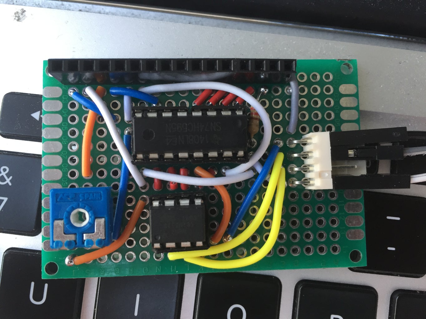
Wiring is relatively straight forward, I have included the Fritzing diagram and picture of the basic wiring
When I made my PCB I miscounted the pins and as such everything is 1 pin off from the wiring diagram
If more details of the wiring as required let me know in the comments :)
Attachments

Step 2: Setting Up the Environment to Program the ATtiny85
This section is about preparing the ATtiny and the Arduino IDE for programming, if you have already programmed ATtiny85 chips before you can skip this step :)
- Prepare the Arduino UNO as an ISP, refer the following URL and follow the steps upto and including step 4 (https://www.instructables.com/id/Program-an-ATtiny-with-Arduino/)
- Add the following URL to your 'Additional Boards Manager URL's in the Arduino IDE preference (https://raw.githubusercontent.com/damellis/attiny/ide-1.6.x-boards-manager/package_damellis_attiny_index.json)
- Once we need to add the boards, to do this click on Tools > Boards > Board Manager, then find the 'attiny by David A. Mellis' and click install
- Now we will need to configure the fuses on the ATtiny85, the following OSX terminal command would set the fuses to enable the internal 8mhz clock along with various other settings, you will need to adjust the bold text to point to the correct serial port
/Applications/Arduino.app/Contents/Java/hardware/tools/avr/bin/avrdude -p attiny85 -c arduino -C '/Applications/Arduino.app/Contents/Java/hardware/tools/avr/etc/avrdude.conf' -P /dev/tty.usbmodem1411 -b 19200 -v -U lfuse:w:0xe2:m -U hfuse:w:0xdf:m -U efuse:w:0xff:m
- Once the fuses are set, you will need to set the Arduino IDE as below
Programmer: Arduino as ISP
Port: Serial port for your Arduino UNO
Board: ATtiny
Processor: ATtiny85
Clock: 8MHz (Internal)
Now that the enviroment is prepared lets upload the code :D
Step 3: Upload Firmware
The code used in this instructable is stored in a github, to ensure you have the latest code please refer to the github (https://github.com/semaja2/LCDTinySerial)
To use the firmware you will need to install the LiquidCrystal595 and Software Serial libraries
Once you have downloaded the code from the github listed above, some adjustments will need to be made to suit your specific needs, luckily all these lines are at the top :)
// LCD Details
#define LCD_CHARACTERS 16 #define LCD_LINES 2// ATtiny PIN Assignments #define SERIAL_RX_PIN 3 #define SERIAL_TX_PIN 4 #define SHIFT_DATA_PIN 0 // ATtiny PIN number connecting to 74HC595 pin 14 (SER) #define SHIFT_LATCH_PIN 1 // ATtiny PIN number connecting to 74HC595 pin 12 (RCLK) #define SHIFT_CLOCK_PIN 2 // ATtiny PIN number connecting to 74HC595 pin 11 (SRCLK)
// General Configration Details #define LCD_CLEAR_ASCII 7 // ASCII code for clearing the screen (use a code that is not often used) #define LCD_NEW_LINE_ASCII 13 // ASCII code for the new line carriage (eg. 13 or 10) #define PRINT_BY_CHAR // Comment out to enable line by line mode eg. only show data after new line
After you have adjusted the various defines, simply upload to your ATtiny
Step 4: Using the 1 Wire Controller
Usage is fairly straight forward, simply open a serial connection from another Arduino at 9600 baud
Once you have a Serial connection, you can start sending text with the Serial.println command, if you are displaying text in a specific layout, then reset the LCD using Serial.write(byte(7)) then send your text to ensure a constant layout
void setup() {
Serial.begin(9600);}
void loop() {
Serial.write(byte(7)); //send Null to clear screen first
Serial.println("First Line");
Serial.println("Second Line");
Serial.println("Third? Line"); // If your screen only has two lines, this will replace the previous lines
}

Participated in the
First Time Author Contest 2016


