

Introduction: 360 LIDAR Module


This instructables is to show people how to easily convert a one directional Lidar sensor such as the Lidar Lite v to a 360 degree Lidar. The reason why I want to make my a 360 Lidar is to get into Simultaneous localization and mapping(SLAM). SLAM , in essence , a navigation technique use mostly by autonomous robot by creating a 2D map of the surrounding environment and countinously updating the map. A 360 Lidar is an essential component for using SLAM because it provide 360 degree distance detection information that is needed to create the 2D map.
Step 1: Concept Design

The design of this 360 Lidar module was inspired by Velodyne Lidar . I wanted to make something circular and have a compact feel to it. This module is not only for the Lidar Lite V/V2. You can also use this for lower end Lidar such as Sharp IR Analog Distance Sensor. Just remember that you will need to modify the mounting plate if you use something other than the Lidar Lite V/V2. I will provided the CAD files in step so you can easily modified the 360 module to fit your sensor.
Step 2: Materials


360 LIDAR Module Parts (All 3D Printed)
- Module Body
- Module Top
- Motor Holder
Electronics
- Lidar Lite v or Lidar Lite v2
- Arduino Uno
- Flip Ring with Flange 22mm
- *Micro Motor
- *Raspberry Pi 2
- *Adafruit Rapsberry Pi Motor controller
- *Turnigy Receiver Pack 2300mAh
Other useful equipment
- Screw Gun
- Jumper Ribbon
- Wires
- Superglue
- Solder Iron and Flux
- Tape
Note:
* This symbol indicate that you don't need these part exactly. For example, you can take replace the Rapsberry Pi 2 and the Pi Motor controller by using an Arduino Motor Shield and control the motor directly with your Arduino. The power supply can be replace with AA batteries. You can also use a much cheaper motor too.
Most of the electronic components I used come from old project and thus it help me save money from buying new parts. This project is really flexible so used what you have first before buying new things.
Step 3: Download Section
The Hardware file contain the printed part for the 360 module. The file include all the CAD drawing in STL and STEP format.
Hardware Mirror 1 : Mediafire
Software file contain programs to control the motor and continuously output distance values .
Software Mirror 1 : Mediafire
Attachments

Step 4: Printing and Painting
I used a XYZprinting Da Vinci with PLA filament to printed all my hardware parts. As a lower end 3D printer, the quality itself is not that polished, but they get the job done . Remember to print all the part with at least 50% infill or they will break very easily. In addition, always turn on support option or else you will get a fail print. You can always remove the support afterward.
In this build , I also experiment with PLA painting with an enamel acrylic silver paint. To be honest, the finish did not look that good an I would dissuade people from trying this. A better option is using spray can or color filaments.
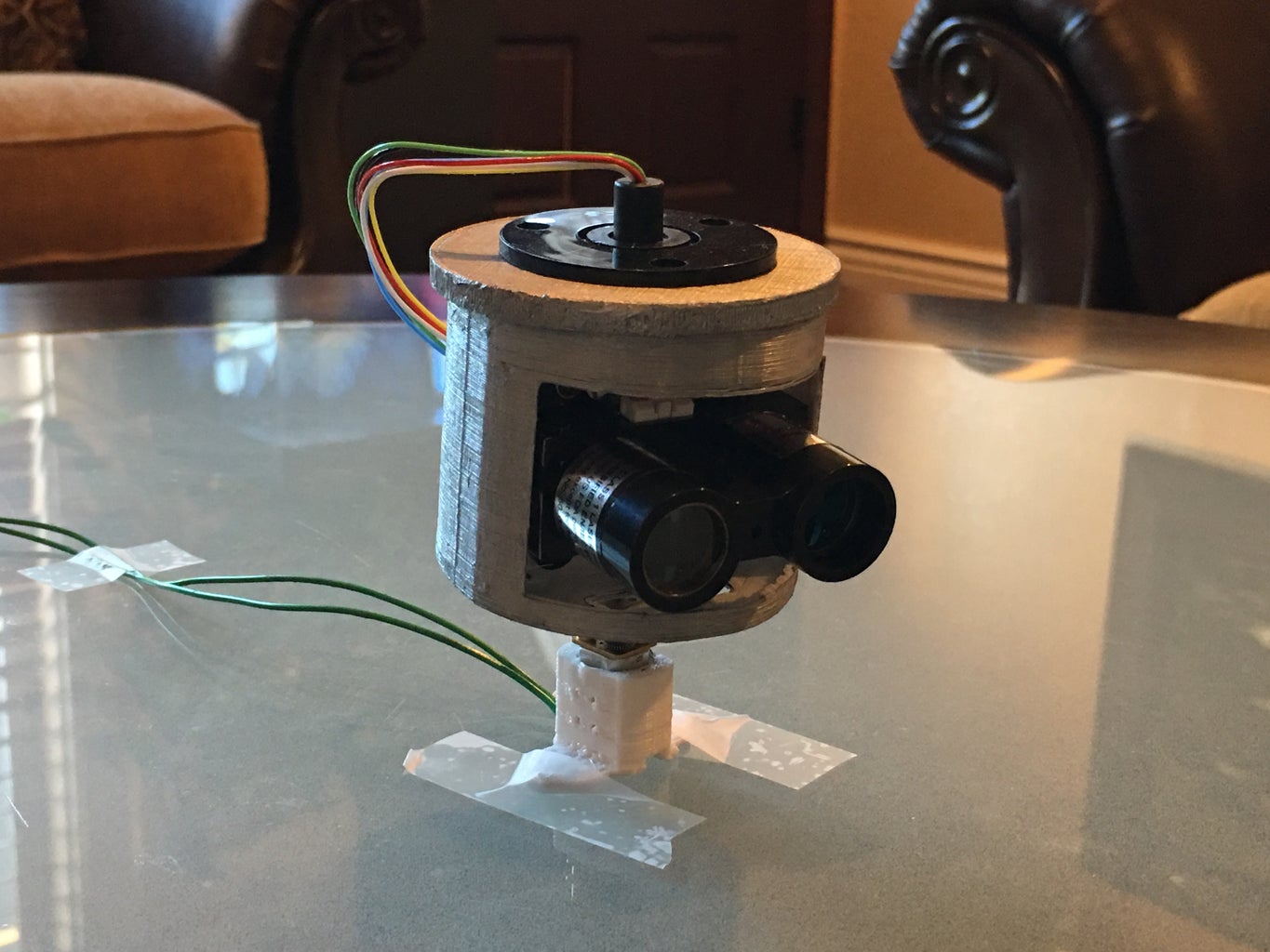
Step 5: The Top and Body Module


This part you will need the Body Module part ,Top Module part,Lidar,Slip Ring, and two screws. Any screw is fine, just make sure that they fit the hole on the Lidar
- Put the Lidar on the mounting plate on the Body Module Parts. Remember that the Lidar connection is facing toward the top.
- Put in the screw. 1 screw on the top left and 1 screw on the bottom right. This should be enough to secure the Lidar in place.
- Now put the Slip Ring on top of the Top Module part. The bigger side of the Slip Ring is facing down and the smaller side is facing upward.
Step 6: Soldering Connection


Now we going to need to solder the connection between the Slip Ring and the Lidar . First make sure you cut down the wires of both the Lidar and Slip Ring down to around 7 to 10 cm . This is to make thing more clean and easier to fit inside the module. If you don't want to solder you can use a female to female jumper ribbon. The connection of the wires goes as follow:
- 5V to Red
- Gnd to Black
- SDA to Green
- SCL to Yellow
If the wires was solder, use a blue or electrical tape and cover up the solder part to prevent connections from touching each other and get shorted.Once this is done, put the Top Module on the Body Module.
Step 7: Motor Casing


This you will need a motor and the Motor Casing parts.
- Put the motor into the Motor Casing. It should fit perfectly.
- One the motor is secure in the casing. Insert the Body Module on the motor shaft. Leave around 2 to 3 cm of clearance between the Body Module and the motor.
Step 8: Wiring

Before you begin wiring, head over to this tutorial to setup your motor controller. Once that is done, you can begin wiring up all the electrical components.
As you go along this step, look at the picture above for reference. Always double check the diagram before you plug something in. The last thing you want to happen is something get damaged due to being shorted.
- The connection from the Slip Ring to the Arduino goes as follow
- Black to Ground
- Red to 5V
- Yellow to A5
- Green to A4
- Next we going to connect the motor to the Motor controller via terminal 1 . Just plug the 2 wires into the first two hole in the board. The polarity don't matter for motor
- Now connect the Turnigy Battery to the Motor Controller. The black wire go to the hole with negative sign and the red wire go to the hole with positive sign. If you connect them correctly you should see a green light, if there are no green light then remove the wire immediately and check your connection setup.
- Power up the your Raspberry Pi and Arduino via USB cable plugin to the computer. The computer USB port provided 5v to power the boards.
Step 9: Software
There are two main software for this part. The first one is the software for Lidar that is written in C and use in the Arduino. The software interact with the Lidar by I2C communication. It allow the Arduino to read distance range continuously,
The second part is a python script that is put in the Raspberry Pi 2 to control the motor. The python script allow the motor to go either autonomous 360 rotation or manual control of left and right.
In the future, I would like to incorporate the Lidar into the Raspberry Pi and create a 2D mapping technique. I am currently looking into the ROS framework since they already have a few pre-built library for SLAM. However, ROS is complicated and it going to take a while to figure it out.
Attachments

Participated in the
3D Printing Contest 2016

Participated in the
Sensors Contest 2016

Participated in the
First Time Author Contest 2016


