

Introduction: 3D Design and Print an Arduino Relay Box


While working on an Arduino project, my friend Tucker asked about the possibility of creating a custom box for his Jeep project. I was intrigued and since we have the time and a 3D printer, why not?
A generic mounting box is around $30 with a lid but was kind of blah. We wanted to be able to change where the box was mounted from, be able to change the orientation, change the access ports as needed, and have a see-through lid with one of a kind knobs to hold it all together. We were also limited by the 3d printer bed size compared to the size needed to be printed.
Inside will contain a PCB board with fuses for power, an Arduino Mega, and a 16 channel relay board for controlling the running lights, brake lights, turn signals, hazard lights, and fuel pump.
Software used for this project:
123D Design by Autodesk for designing the box and parts and creating the .stl files
Cura 3.6 for slicing the .stl files
ATHD's Marlin on a modified Anet A8/A6 Hybrid 3d printer
Hardware needed for this project:
PLA(polylactic acid) filament, 1 roll black (Amazon)
Blue Painters tape(Amazon)
1/4 in x 20 nuts x4(Amazon)
1/4 in x 20 x1 inch bolts x4(Amazon)
1/4 in flat washer x4(Amazon)
Arduino Mega(Amazon)
Sainsmart 16 relay board(Amazon)
fuse board(Amazon)
Step 1: Design Phase


If you don't care about the design phase, skip down to step 3 to see the STL files and settings used for printing.
We knew what our end goal was so we began by measuring all of the components and the mounting points for each board. We laid out the boards and determined that the minimal distance between them could be 3mm. With 3mm between and around each board and a 6mm wall thickness, our box was 195mm by 200mm; almost filling the 220x220 build plate of the printer.
Mounting posts for the boards:
Relay Board: I started by creating one post, 6mm diameter and 15mm tall. Select ,Copy and paste a second cylinder, it should appear in the exact same spot as the first. Move the second cylinder 82mm along the x axis. Then select both cylinders, copy paste and move this set 171mm on the Y axis. This gives us the 4 mounting posts for the 16 channel relay board. Select all 4 cylinders and group them so the distance between them cannot change.
Arduino Mega: Create another cylinder 6mm by 15mm; select ,copy, and paste for your second one. Move the second cylinder 48mm on X axis and -5mm on Y axis. Because all four holes are in slightly different positions, I completed the third and fourth posts separately. The third post should be copied from the first and moved 75mm on Y axis; the fourth copied from the second and moved 83mm on Y axis. This will place the third and fourth 48mm apart on x and 1mm difference on y axis. Group these 4 cylinders separate from the first set
PCB Board: Just like the relay board, these can be done as pairs and moved 16mm apart on X and 76mm on Y. Group this last set of posts and we can begin laying out sets together.
Start by aligning all of the post sets to one end, then move the mega set along X until the two closest posts overlap. Continue to move until there is 9mm between the posts centers(4mm to edge, 3mm between, 2mm to edge). The PCB Board posts will be positioned beside the Mega but only requires 7mm between post centers to maintain 3mm gap. Now that the posts have been positioned as in picture 1, we can group all of them together.
The Box:
I started with a cube and expanded to 195mm by 200mm by 50mm. Use the shell function leaving a 6mm thick wall and floor.
Next I created a 15mm cylinder and aligned to the inside corner of the box. After selecting the cylinder, we tilted the bottom out 15 degrees on each axis. Using the plane cut feature, I trimmed the top even with the box and both sides so the cylinder did not extend outside the box. Do not weld or combine the box and cylinder yet!
Create a 10mm hexagon that is 6mm high and a 6mm cylinder 20mm long. Align these two and weld them together to simulate the nut and bolt we will embed in the 3d print. Align the bolt and cylinder on X and Y and lower the bolt along Z axis until the nut is at least 2mm into the body of the cylinder. Now use the subtract function to create a void of the simulated nut and bolt into the cylinder. At this time, I copied the cylinder and moved each one to a respective corner and welded them to the box. I turned the setting to only show outlines to see the void as seen in the picture above.
At this point, I created a 3mm Filet around the floor of the box. this is used for strengthening the joint between the two and gives a 3mm reference line for placing the grouped posts on the floor and welding them in place.
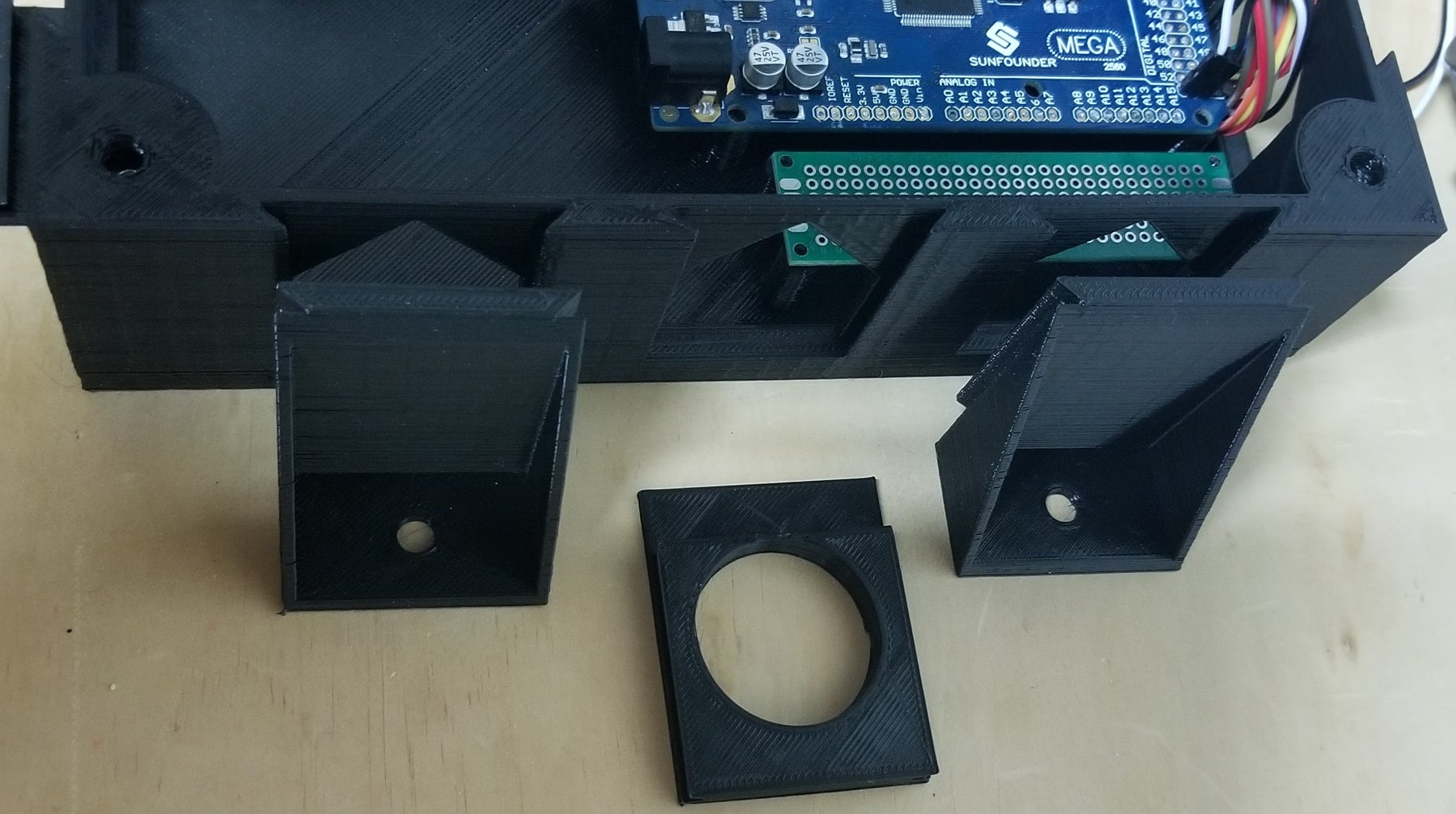
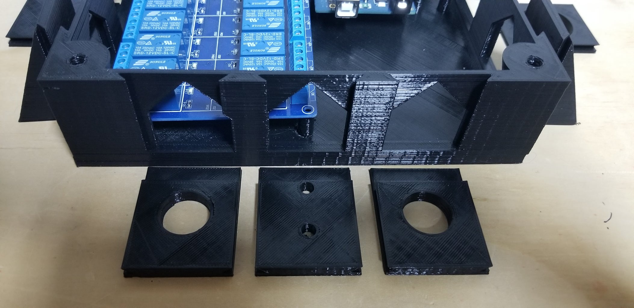
The access ports for universal mounts have a 45 degree top to avoid having to print using support and were created by combining a flat plate(48mm with 4mm bevels), a 40mm cube and a cube rotated 45 degrees and then resized to 40mm wide. I welded these together and placed three per side. I aligned the outside edge and top, then spaced them equally across the side before using the subtract function to cut the access holes. This also left a 2mm bridge for support all around the top of the box.
Universal Inserts:
These are the most customized for this project. I started with a blank plate(40x2x50) and added a beveled plate(48x4x44) to the back. The bevel perfectly aligned with the bevel cut into the side of the box and allows the part to slide in and out. Once the blank was created, I started making variations for all the different components to be attached; a 20mm cannon plug, 32mm cannon plug, vertical and horizontal holes for power lines, body mounts with holes for bolting to the Jeep.
The Lid:
I placed a cube on top of the box and extended it 2mm past each edge of the box and 4mm down the sides. using the subtract function gave a perfect cutout along the bottom and then I used the plane cut to slice along the interior wall and around the bolt mounts to remove the center of the lid so it can be replaced with plexiglass and show off the hardware inside
The Knobs:
These were the final design to complete. They started as a cylinder 40x40x20, I added a cylinder 10x10x20 to the side and did a circular pattern to evenly space 5 more around. Subtract function and a chamfer to the top and bottom all around completed the outside. A 10mm hexagon and 6mm cylinder were subtracted from the center all the way through for the bolt to be held and turned.
Step 2: Preparing for Printing
Now that the design is completed, I exported all the files from 123D Design as STL.
I attempted to print these in PETG for the additional strength, UV protection and heat resistance but was unable to get a full print due to the dust in our current environment. I changed to standard PLA filament because Tucker assured me the strength would work and the parts would not be exposed to heat or UV.
Each part was imported to Cura and rotated so supports were not needed.
All of the interchangeable pieces were reduced to 98% on the Y axis because I designed them with zero tolerance.
Then I sliced using the following settings:
Nozzle-210C
Bed-50C
0.2mm layer height
Flow rate increased to 102%
50mm/s speed
2 line skirt except lid because it would not fit build plate
cooling fan at 100% starting on second layer
20% infill GRID
No support except for mounting tabs
The main part of the box also got a post processing event added. After slicing with these settings, I scanned through the layers until I found the top of the hexagon voids for the 10mm nuts. At that layer, layer 230 I think, I added a filament change and resliced the file. There is a pause option in post event processing but the pause is only momentary and the machine will continue printing, filament change sends the machine into standby and waits for user input before continuing. the pause will work if you are standing at the machine when it pauses and you catch it just right but for a long print I find it easier to use the filament change command.
Each of these were saved to the SD Card and transferred into the printer.


Step 3: Printing, Failing, Printing


All of the hard work is done, time to sit back and watch the printer bring this idea into reality.
I started with the mount as it is the only piece requiring support to be printed. I multiplied the file in Cura to print four at a time to reduce downtime between prints. All good so far.
I moved on to the blank pieces and printed them, no supports and they came out great.
20 and 32mm hole pieces were next and still running great.
The lid was the shortest print at 3 hours and failed about halfway through. The corners lifted and the entire piece warped until the nozzle could not move past it and finally broke free of the bed. I had to try this print two more times before it fully printed correctly. For the third print, I turned the heated bed temperature up to 60 degrees Celsius. This kept the entire part warm so the temperature difference didn't warp and lift the corners.
And now, the box.
With the settings mentions before, this print is 18 hours and 56 minutes, not including wait time during the post event filament change. I have a severe dust problem and the power running the building is from a diesel generator that I don't control. I have never been so nervous to start a print as I was for this. All day the printer hummed and ran and printed away. In the ninth hour of printing as the final layer of floor was being put down, the power went out. I swore, I cried, I walked away and went to bed.
The next morning I grabbed another friend that runs a 3d printer and we discussed options. Remove the print and start over? Can we recover the file and start in the middle? Start in the middle with a clean plate and glue them together? We decided to try and restart the print in the middle and see if it held, worst case was to stop the print and start over from the beginning.
Modifying the G code:
I pulled the SD card back to the computer and opened the gcode file in Notepad.
We knew the power failed near the end of layer 30. So I selected all the text between layer 1 and layer 31 and deleted it.
I also know the home(0,0,0) resets when the printer loses power. I found the G28(auto home command) and deleted that.
Those were the only two changes I made to the G code but I still needed to reset home to continue without an offset on X or Y axes. I couldn't use the auto home because there was 6 mm of PLA covering the Z home spot on the build plate.
I disabled the stepper motors and manually moved the print head to the very front left corner so it would not hit the print during the next maneuver.
I used Marline to move the Z axis down to -6.0mm(30 layers times 0.2mm per layer), then powered off the printer and powered back on. The Z axis was now set to 0 at the build plate.
I used the X and Y home commands to set those respectively and started the modified G code to print.
IT WORKED!
The printer jumped up 15 mm just like after homing and moved straight to the nearest corner and began printing like it had never stopped. It didn't even notice the tiny gap where the last of layer 30 didn't print. I kept watch over the printer the rest of the day and it hummed and printed almost to the top where it paused and let me drop in the nuts. I clicked continue and the printer finished with no hiccups at all.
Step 4: Assembly


All of the parts have been printed and taken back to our room. Tucker and I are very happy with how this turned out and are planning some minor modifications to make it even better.
The Relay board, Arduino, and PCB Board are ready to solder and wire.
Holes have been drilled and we are waiting for screws to secure the boards.
The initial layout has determined where the mounting tabs and access panels need pushed into place.
I am waiting on the plexiglass to be delivered to fit in the top of the box.
The lid fits snug and the knobs hold it all together just beautifully.
Step 5: Final Thoughts
I took this idea from the initial question to reality of printed box in about 2 weeks, I know it can be improved and plan to address this so I can pass along updates in the near future.
The open space below the Arduino Mega was designed to be there, that space will be used for different modules depending on where this box is mounted. Either a Bluetooth module, GPS Module, or Raspberry Pi are planned to go into that space.
123D design is no longer supported or available from Autodesk, but I learned 3d modeling on that software and will continue to use it until I am comfortable with Fusion 360.
If you like this or don't, have a suggestion for improvement, or want more detail to create your own; send me a message.
Thank you for reading through this.
Tim

Participated in the
Epilog X Contest


