

Introduction: 4x4x4 LED Cube Using Arduino
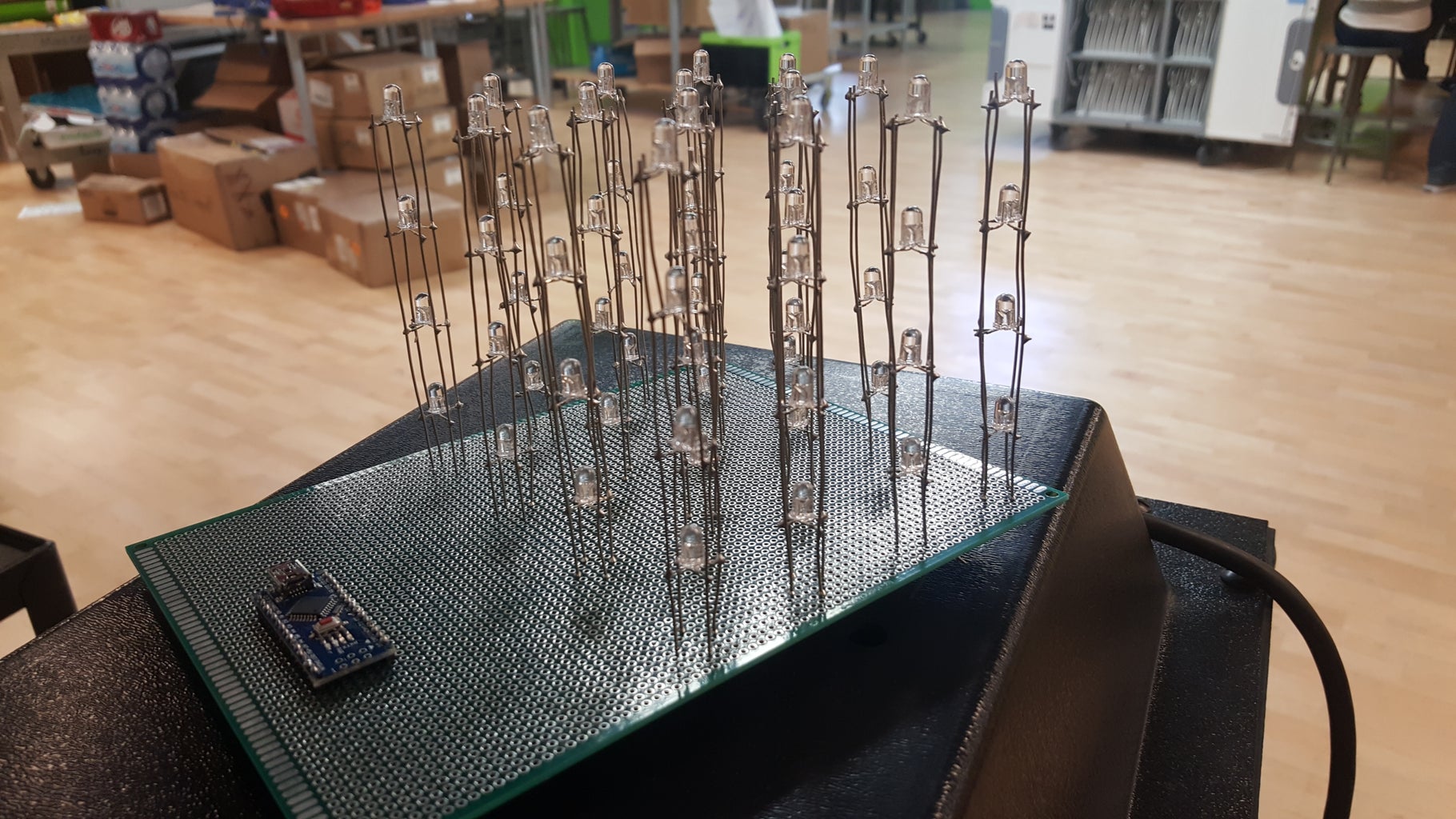
I set out to build the 4x4x4 Charliecube using an Arduino Nano. The cube itself is pretty tough to build, starting with the actual soldering all the way through what can be some messy code. Soldering experience is definitely required.
Materials I would say are needed:
- Some sort of breadboard big enough to house the whole assembly. I had a hard time finding one that would work but the one I went with is here:
- 64 (Should have 5-10 extra in case of improper soldering or bad LEDs) cathode RGB LEDs, I bought mine from Amazon.
- A 3D printer to 3D print the tower tools would be very helpful. This is not required but cut my soldering time in half if not more.
- Soldering gun/solder
- I used a helping hand to hold the tool while soldering but again this could be done without it.
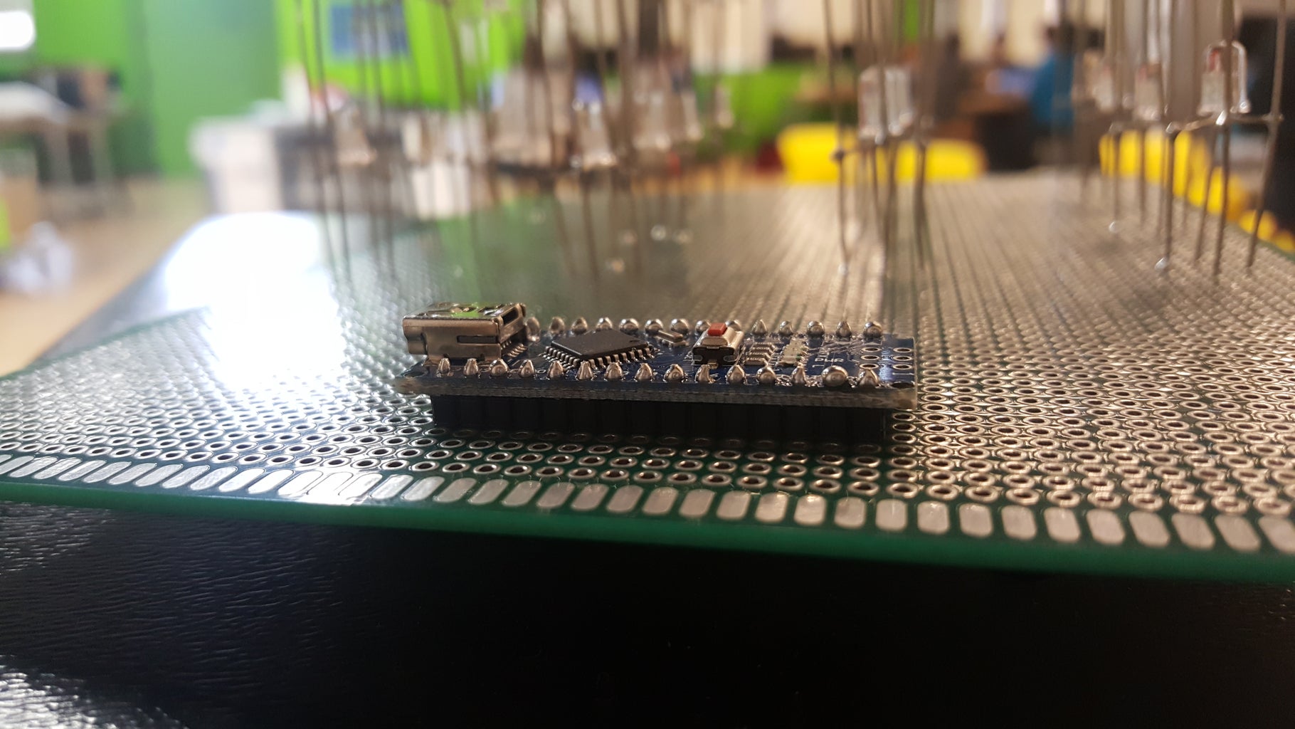
- Arduino Nano and USB Cable (You can probably get away with a different type but this fit right in the board and made it look the cleanest)
- 20 Gauge Wire, which was somewhat unique and hard to find. The 20 Gauge is perfect for the towers and will hold them in place. I used a lot of it, I estimate probably close to 40 feet.
- 22 Gauge Wire, used to wire the towers to the nano on the underside of the board
- Wire Stripper/Cutter
- Some form of standoff for the board
Notes:
I used two different sites extensively during the building of the cube.
Gunderson.net - link here helped me with the 3D tools and showing me exactly how to implement them. Some of their photos are used throughout this guide.
Asher Glick - link here helped me with the libraries and starter code as well as the wiring diagrams to get this project off the ground. All of the wiring diagrams come from this site.
Step 1: Bending the 64 Cathode RGB LEDs

This step while easy is very important. Using the 3D printed tool saved me a lot of wasted LEDs. Here, you put the LED in the tool and bend in the following order. I oriented the LED so the tallest lead was in the second position from left.
- Tallest lead goes up
- Leftmost lead goes left
- Rightmost lead goes right
- Leed to the immediate left of tall lead goes down
Doing this correctly ensures no wiring issues when going to solder the towers.
Step 2: Soldering the Towers


This step is definitely the hardest. You will have to find the best way to solder that works well for your setup. The 3D printed tools are definitely very helpful here.
The way that worked the best for me is as follows:
- Cut the 20 Gauge wire to length, you want it to be probably 1.5 inches bigger than the tower for extra room and wire to solder to the PCB board.
- Place wire on the tool and solder your first LED to that wire. Make sure that the LEDs are in the same orientation for all of the towers you build. This is key in ensuring no software issues.
- Cut another 20 gauge wire for the other side, same length.
- Solder the first LED to that wire as well.
- Gather your second LED and rotate it 90 degrees from the first one. Solder it to both of the wires.
- Go down the line to complete the 4 LEDs soldered to the two wires.
- Use the removal tool pictured here to remote the LED tower from the 3D printed piece and flip it over and put it back in
- Using 2 more 20 gauge wires, solder the 2 unsoldered leeds to these wires.
- Repeat this process for all 16 towers.
Step 3: Testing the Towers
It is important to test each tower to ensure that they are all functional and soldered correctly. The best way to do this is to wire up a wire to ground and a wire to 5v and hold the ground constant and rotate the 5v around the other 3 pins. Then move the ground and check each of the other LEDs. You should see the colors change between red, green, and blue on each LED.
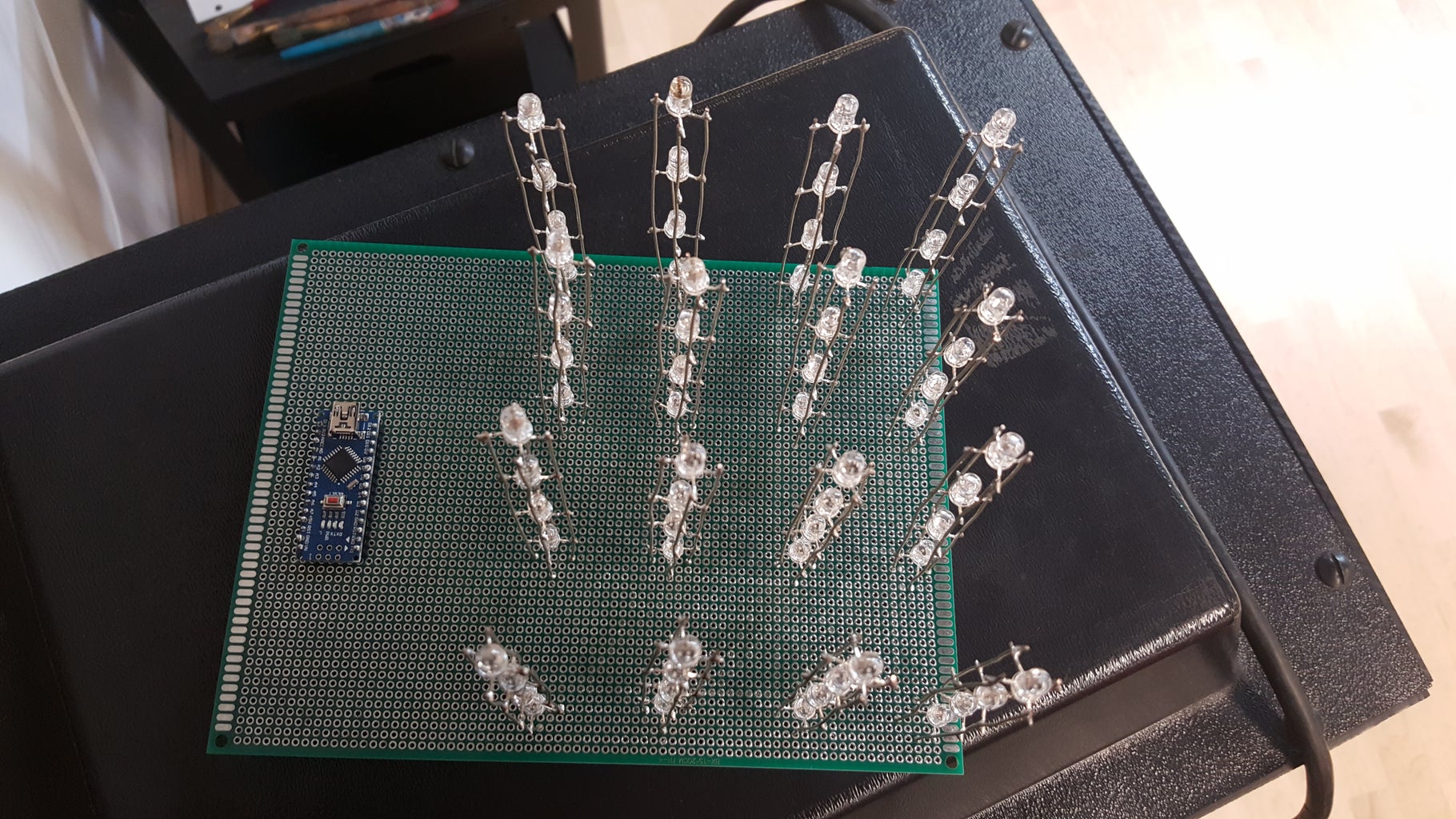
Step 4: Soldering Towers to Board


Mapping your board out is necessary to ensure that your lights are evenly spaced. The closer together they are, the better any effects you develop will look on it. This will vary based upon the PCB board you have chosen. Once you have the spacing correct, solder each tower into the holes from the underside of the board. Doing the corners first and then moving inwards. Make sure the towers are all in the same direction.
Step 5: Wiring the Underside of the Board


The guide I used suggested to do the wiring in groups. This seemed to work the best. Use the attached photos to wire up the 16 needed wires. Once that is done, wire it up to the Arduino as follows:
- Wires 13-16 are wired to the analog 0-3 pins.
- Wires 1-12 are wired to the digital pins starting from digital 2 to digital 13.
Step 6: Programming
The libraries I used to program mine can be found at the site linked below. Download them and experiment with the code to make cool shapes and displays. This is where the cube is a lot of fun.
Link to the site for the libraries: Link
Step 7: Wrapping It Up
Was it worth it? Did you enjoy soldering 300 different leads? I definitely enjoyed building my cube and I hope that the experience is the same. The possibilities with development here are endless.


