

Introduction: AC to DC Power Using a Full Wave Rectifier
AC is used to transmit power over long distances. The power we get from the electrical outlets in our home is AC power. However since most modern electrical appliances use DC at some level, we need to know how to effectively convert AC power to DC power. We can do this using a circuit known as a full-wave bridge rectifier.
Reference: Basic Electronics: An Introduction to Electronics for Science Students, 2nd Edition by Curtis A. Meyer.
Step 1: List of Parts
1. Transformer x 1
2. Diodes x 4
4. Electrolytic Capacitor x 1
5. Resistor x 1
6. Wires (as needed)
AND
Either:
7. Voltage Regulator x 1
Or:
8. Zener Diode x 1
9. Additional Resistor x 1
(either we can use the voltage regulator, or the zener diode and another resistor)
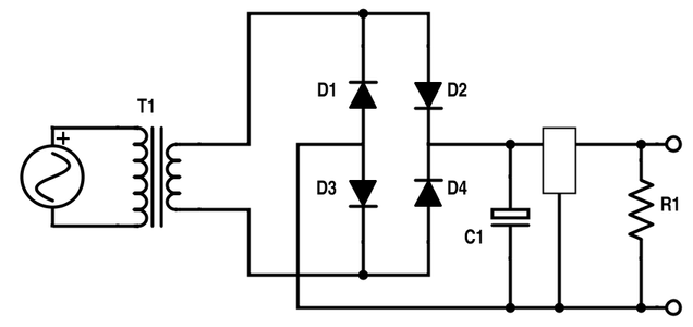
Step 2: The Full-wave Rectifier

The full-wave rectifier is built as shown.
The transformer (labelled T1) can be used to step down the AC voltage supply from the electrical outlets to a lower voltage. Depending on the country, the AC voltage in the outlets can vary from 110 V to 230 V which are very high voltages and can severely electrocute someone if they come in contact with the voltage. The transformer can lower this voltage and thereby reduce the danger.
The reduced voltage from the transformer now goes through one of the diodes. Remember that diodes only allow current to flow in one direction (hence the arrow-like shape). Therefore, which diode the current will flow through depends on whether the AC voltage is in the positive half of its cycle or the negative half. During the positive part of the cosine cycle of the AC voltage the current flows through D2 and D3. During the negative half, the current flows through D1 and D4. However the voltage at the ends always has the same polarity. Hence this part of the circuit effectively gives us the absolute value of the input cosine voltage (after being stepped down by the transformer) minus 2 diode drops of voltage (recall that the voltage drop across diodes is virtually constant and ~ 0.65 V).
Step 3: Buffered Full-wave Rectifier

Though the voltage is of only one polarity now, it is still far from DC since it varies from 0 to the amplitude of the input voltage minus 2 diode drops. We can help smooth out or buffer this voltage by using an electrolytic capacitor (C1 on diagram) to build an RC circuit, as shown. Be careful that the anode of the capacitor (the small box) is at a higher voltage than the cathode.
The AC input voltage fluctuates usually with a known frequency. We must choose our resistor R1 and capacitor C1 such that the product of their resistance and capacitance (R*C) is much greater than half the period of the input wave. In short,
R x C >> T/2
where T is the time period of the input wave.
If we choose our resistor and capacitor right, the capacitor will charge up when the input voltage wave is near its peak but will not have time to fully discharge when the input voltage wave is near its trough. Hence the output voltage will be more constant or smoothed out.
Step 4: Voltage Regulator


Now we have rectified the AC voltage (made the polarity of the output only positive) and smoothened it out a little bit. We can make it a true DC source by adding a solid-state voltage regulator. The regulator is shown as a rectangle on the first diagram. This will produce a constant output voltage with very little variation.
This can also be done using a zener diode in parallel with a resistor, as shown on the second diagram. When connected in a circuit, zener diodes are reverse biased. This means that current is supposed to flow in the opposite direction in a zener diode as compared to a regular diode (in a zener the higher voltage is at the tip of the arrow). They are designed such that the voltage drop across them is constant when they are reverse biased. Hence a zener diode adjusts the current flowing through it so that the voltage drop across it remains the same. This ability of the zener diode is used to stabilise the output voltage to changes in the input voltage.
Since the zener diode is in parallel with our output, the voltages across them both will be the same. Hence, you can choose your zener diode based on the voltages you're working with. For instance, if you want a 5 V output DC supply, a 5.1 V zener would work. Check the power rating of the zener. The maximum current that can flow through the diode is equal to the power rating divided by the voltage of the zener (I = P/V). The resistor (R2) is used to limit the current in the circuit so that this maximum current limitation is not exceeded. Calculate the minimum resistance of the resistor (R2) by dividing the maximum voltage across the resistor by the maximum current through the zener. This means Minimum Resistance of R2 = (V of Supply - V of Zener)/(Zener Current). This accounts for the worst case possible in which all the current goes through the zener and none to the output, and ensures our zener is safe.
With this, we have effectively converted our input AC voltage to DC.


