

Introduction: AND Gate for Logic Circuit Applications


Logic gates are the fundamental building blocks of digital circuits; it's how computers record and transmit information!
The most basic logic gates (like the AND gate) help you interpret two binary inputs to control a single output. Binary means that the inputs leading into the gate have two possible states like "on or off." Some examples would be two switches that are either "open or closed;" two light sensors that are either "bright or dark;" or two temperature sensors that are "hot or cold." The single output might be an LED that is either "on or off."
In the case of the AND gate, if both inputs are ON then the output is also ON. Any other combination of inputs results in the output being OFF. The truth table shown above helps to illustrate this pattern. The venn diagram next to it is another way to visualize the AND gate. The area of overlap between A and B is highlighted because the only way to make the output turn ON is when inputs A and B are both ON.
An example of an AND gate project would be a gumball machine.
Input A: Coin inserted or not inserted
Input B: Button pushed or not pushed
Output: Gumball dispensed or not dispensed
In order to dispense a gumball, you have to insert a coin AND press the button!
In this Instructable you will learn how to create your own AND gate with Circuit Scribe ink, transistors, and resistors.
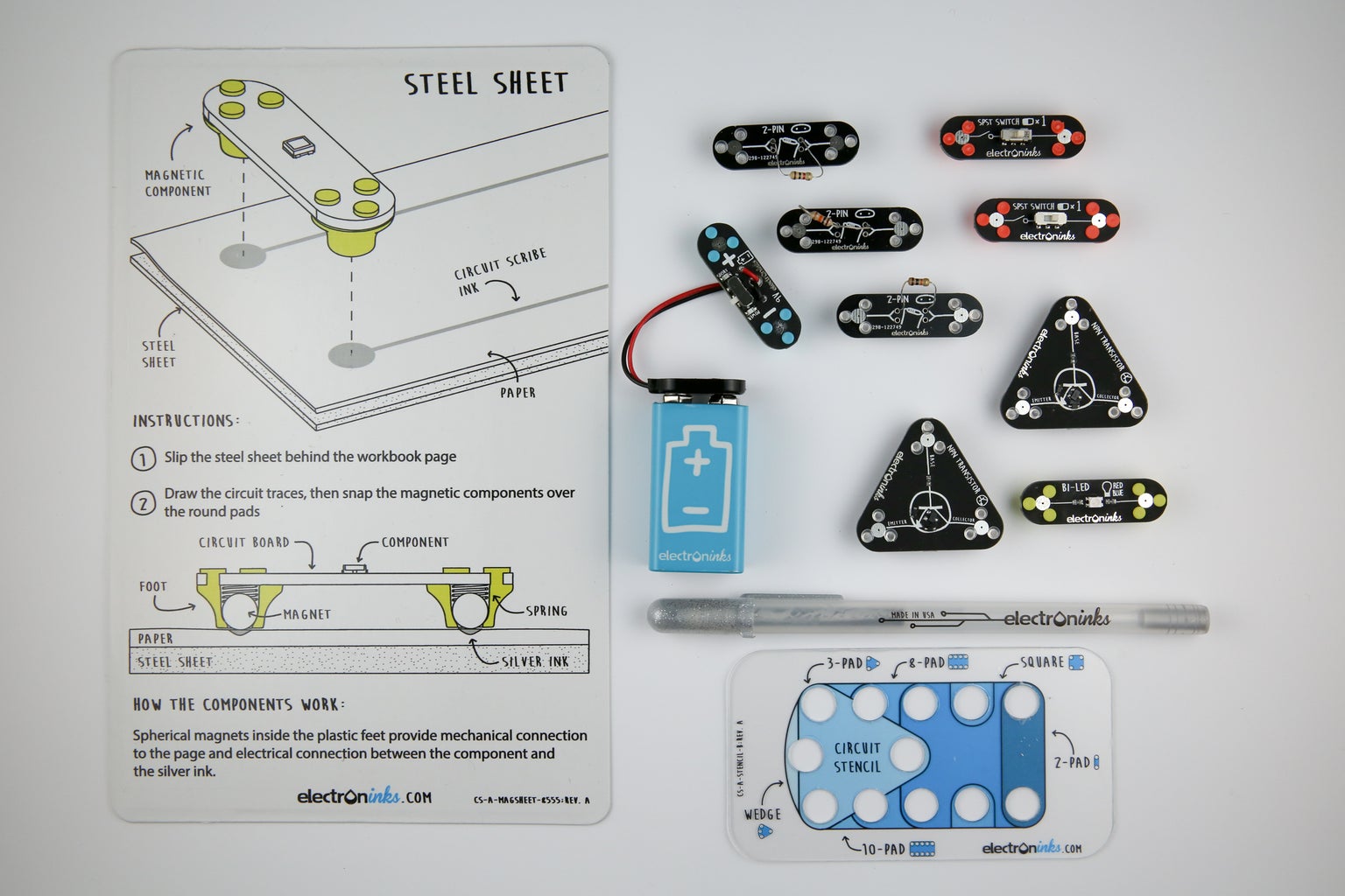
Materials
- Circuit Scribe conductive ink pen
- Sheet of paper (preferably photo paper)
- Metal Sheet
- Circuit Stencil
- 9V battery and adapter module
- 2x NPN Transistor modules
- Bi-Directional LED module
- 2x SPST Switch modules
- 3x 2-Pin modules
- 2x 10 k-ohm resistors
- 1x 5 k-ohm resistors
These materials were purchased on the Autodesk 123D Circuits website.
Step 1: Simulate the AND Gate
Here's a 123D Circuits project illustrating how the AND gate works. Both of the input switches need to be turned to the ON position in order to light up the output LED. If one or both switches are OFF, the LED will be off. You can press "Start Simulation" to try it out.
Step 2: Setting Up Your Work Area

Begin by placing your metal sheet under the piece of paper. The metal sheet will allow the component modules stick to the circuit via the magnets in their feet. The paper will act as your circuit board material.
Step 3: Draw the Circuit


Using the the schematic shown we can start building our AND gate. Each component on the schematic represents an Electroninks module. Use the stencil to draw a footprint for each module. It is easiest to place the footprints in roughly the same location on your page as they are in the schematic. Once all your pads are drawn you can connect the module pads by following the schematic.
Step 4: Connect the Modules

Snap each module onto its corresponding foot print. This action will complete your circuit! Make sure the battery module and both switches are in the off position.
Step 5: Testing the Circuit

When you are ready, switch the power module on. Now try flipping the switches. Try a few different combinations of the two switches being ON and OFF. If you have correctly constructed the the circuit the LED will only light up when both switches are in the ON position.
Step 6: How Does It Work?


The NPN transistor is a current amplifier. Small current between the base and emitter is used to control a larger current between the collector and emitter. This is shown in the diagram.
In our schematic we are only providing a current to the base of either transistor when its switch is in the ON position. This means that when both switches are OFF no current can get to the LED so it cannot light up.
We want to create a situation in which current only flows through the LED when both switches are ON. In order to do this, we connect the emitter of one transistor to the collector of the other.
- If the second switch is on but the first is not, the first transistor will not let current pass.
- If the first switch is on but the second is not, the second transistor will not let current pass.
Good luck with your AND gate construction! Leave us a comment to let us know how your circuit works!


