

Introduction: RPiScope: a Raspberry Pi Microscope, Build From Laser Cut Acrylic Parts


Work in progress. Version: 29 Nov 2015
Step 1: Introduction
Step 2: Taking images & example images (have a look on the fly movie)
Step 3: Building instructions
Step 4: Reflected light vs. transillumination microscopy
Step 5: SVG files and other instructions
Introduction
Based on the RPI camera and LEGO brick-based microscope I had presented earlier ( A-Raspberry-Pi-camera-based-microscope-built-from- LEGO ), I have constructed a similar microscope build from Plexiglas parts. So now you may build your microscope even w/o having a large LEGO collection. One thing missing in this prototype is the adjustment gears of the LEGO version.
The maximum resolution of the microscope is about 5 µm/pixel. At high resolution only a small area will be in focus and you will see an effect called chromatic abberation. You may use this microscope to analyse objects in the range from a 20th of a millimeter to 5 mm. This means fruitflies, hair, salt and dust, but not individual cells, e.g. from blood or cell culture.
Below you will find a description of the device and the information necessary to build one on your own.
The prototype version presented here had been constructed in a way that would allow easy assembly from pre-produced parts and subsequent disassembly, as long as long the parts are not glued together. This was intended to allow modification and optimization the microscope, and adaption for special applications, if required.
I am currently working on a simplified version that will be easier to assemble and a bit cheaper in production. In addition I am working on better illumination and the optimization of the optics. My aim is to design a building kit that would enable a science class to build their own microscope, at costs (w/o RPi) of << 100 €.
Let me know if you would be interested in the kit, or just the SVG files and instructions, and please indicate if it should be used for educational, private or research or commercial use. Any ideas for improvements as well as for science projects, like time lapse videos of the growing crystals or mold, would be welcome.
Parts needed:
- a Raspberry Pi 2, keyboard, mouse, monitor or TV
- a WaveShare B-camera (WaveShare B), I got mine at Sertronics, Berlin, Germany, and a 50 cm camera cable.
- a set of pieces cut from 3 mm acrylic/Plexiglas plates, as defined by the SVG files (see Step 5).
These could to be ordered at your local laser cutting service, e.g. Ponoko in the US, Formulor in Germany or RazorLab in the UK. Just upload your SVG-files at their web site and order.
- a set of pieces of 10x10 mm Plexiglas beams (in total about 170 cm), available e.g. at Modulor, Berlin.
- a number of Plexiglas sticks/dubles with a diameter of 3 mm and a length of about 8 mm and/or
- glue for Plexiglas, as dichloromethane (handle with care, it is toxic!) and/or super glue
- six 10 mm M2 screws and ten M2 nuts. M1.6 screws and nuts would be better, but are not so easy to get.
- for illumination: a 1,6 W LED lamp (12 V), a 9 V block battery, cable and battery adaptor, a small switch.
Costs:
- the WaveShare B-camera is available for 22 US$ at WaveShare, or for about 25€ at Sertronics.
- the laser cut plates will cost about 30€.
- 2 m of the 10 x 10 mm acrylic beams cost about 14 €, e.g. at Modulor, Berlin
- M2 screws and nuts, about 5 € (Bauhaus, Berlin), M1.6 x 10 screws and nuts: about 11 € (Conrad.de)
- a Raspberry Pi with SD card, keyboard and mouse will cost about 60- 70 € (in case you do not have one already).
Basic layout:
The microscope consists of a base plate, a sled tray for objects or object glasses to be placed on and a "tower" to hold the plate on which the camera is mounted. Object sled and camera plate can be moved orthogonal to each other, allowing precise placement of the camera above the object. To focus the camera, you must manually turn the camera objective. I had placed a LEGO rubber wheel at the objective to get a better grip.
To adjust the distance between object and camera you may place the object on a tray with a certain heigth or, for a permanent solution, may adjust the length of the colums of the camera tower.
The majority of the parts can be ordered via internet at laser cutting services as Pokono.com, Formulor.de or RazorLab.co.uk and are made from 3 mm acrylic/Plexiglas. I have attached a description as pdf and the required SVG files, which are based on the 181 x 181 mm (P1) plate form used by Pokono, Formulor and RazorLab.
In addition to these parts you will need a set of beams made of 10 x 10 mm profile pieces, preferentially from Plexiglas. You may cut them yourself, but I would recommend to ask a professional service.
Alternatively you may built your microscope from other materials as well, e.g. from plywood and aluminum profiles.
In my construct you may find a large number of 3 mm holes. They are intended to be used in conjunction with 8 mm long 3 mm plexiglas dobels to connect the plates with the beams. This does allow assembly and subsequent disassembly of the parts. If you plan to glue the parts together (e.g. using dichloromethylen or super glue) you may eliminate the holes in the SVG-files, as this also reduces cutting costs. The SVG files can be modified using Inkscape ( www.inkscape.org ) and various other programs.
Possible improvements:
An optimized, much easier to assemble version is in development and will be presented here when later.
- as camera objectives by other suppliers (e.g. Vision Dimension) fit into the camera's S-mount, it is possible to optimize resolution and/or image quality. In first experiments 8 mm and 12 mm lenses work well (see example images) but may require some modifications of the microscopes' layout. A more elaborate comparison may follow.
- illumination, especially for transmitted light microscopy, shall be optimized.
COB LEDs (available from Banggood) are very small and strong, and give a more homogenous light field.
They turned out to be a good solution for reflected and for transmission light microscopy.
- gears to position object tray and camera.
The LEGO version had a nice worm gear for the camera and a gear wheel with toothed rack for the object tray. I have adopted them for the next iteration of the acrylic version (see step 5).
- A number of parts can either be eliminated from the current construct or repaced using other, less expensive or easier to handle materials. In addition the assembly process shall be simplified.
Please let me know your suggestion and ideas.
Step 1: Taking Images & Example Images


I have preferentially been using PiVision to take images.But there is a number of other good GUIs for raspistill and raspivid available as well. Alternatively you may also run raspistill from within Mathematica, where you may directly use the very mighty image analysis functions that come with the program for image analysis.
PiVision gives you a good option at "Main" to perview the image and see if the camera is focusing on the area of interest. Then you may change to the tab "Photo" and take the image. Change the option settings to expand the preview image, so you may see more details and be able to re-focus. Change the "t" parameter to 20.000 or higher, so you will have enough time to optimize the focus and area selection before the image is taken.
Focussing can be a bit difficult without moving the camera.In the case of the LEGO-version the camera was locked by a gear that also allowed fine adjustments, and is it planned to implement a similar construct in later versions of this microscope as well.
As the focus depth of the system is extremely small, you will have to focus on the very detail you are interested in.
The area of focus is constrained to an area the center if the image. You may use GIMP or a similar program to crop the images to the relevant area.
An effect called chromatic aberration result in a color fault, so that the center of a white image is tinted yellow while the outer area appears violett. As achromatic lenses are practically not availabe in M12, the best option for corrections seems to be the application of a specific filter in post processing.
Another artefact might be an effect caused by the white compensation function. Even if an object is bright red, it will appear white if no other color is seen.
You may also take movies in the h264 format. There is one available at the examples.
-------------------------------------------------------------
Here you find a variety of example images that where taken with the device.
Most of them were taken with the 12 mm objective I ordered at Vision Division.
In many cases they where cropped to a selected area, some resized or turned
. No other manipulations where performed.
If you would like to get a real impression of the resolution, I would recommend to download some of the images.
Images 1 - 2: Images of a very tiny spider with a body length of about 2.5 mm
Reflected light (#1) and transillumination (#2) images.
Images 3 - 5: Images of a small fly with big wings.
The fly's body (#3), and close ups on the fly's eye (#4) and its wings (#5).
Images 6 - 8: Images of small glass beads, with an average size of 100 µm.
I have stained them and use them as size standard.
Image 6: The orange lines are the patterns from a millimeter paper
Image 7 - 8: wet beads, in reflected and transillumination views
Images 9-11: An image of the part of a small blue flower (#9);
the image on my TV screen, with the object below (#10);
the flower (#11).
Image 12: The tip of a ball pen
Image 13: The tip of a insulin pen needle
Image 14: A 3 M Nylon screw
Image 15: The inner of a small yellow flower
Image 16: A slice of onion
Images 17 - 19: Details of the yellow inner part of a daisy
Images 20 - 21: Transillumination and reflected light views of a dried poppy petal
Images 22 - 25: Tiny glass particles stained with a yellow and orange fluorescent dye,
illumated with normal (#22 & #24) and blue (#23 & #25) light.
Shred particles and beads made of glass with inner channels and an average size of around 100 µm where stained with orange and yellow flourescent dyes respectively. Upon illumination with blue light from a blue light LED array (Phlillips goLITE), they gave a bright fluoresence. As you can see, the shred particles with their open channels were stained well, while the beads where very inhomogenously stained.
Images 26 to 30: Details of a common fly
I had caught the fly in a glass and intoxicated it with Dichloromethane, trying to kill it. Here you find some of the images of its head. Making the photographs, I was surprised to find that the animal was not completely dead.
Which resulted in:
Movie 1: A fly sticking its tongue.
So here is a somewhat unusual movie featuring that druged fly. H264 is the standard video format of the raspicam.
You may use the VLC player to watch h264 movies on a Windows-System.
Images 31 - 36: Details of a caterpillar
I came across a caterpillar. In November, in Berlin. Weird.
It died for science instead of the cold. Some details.
Attachments

Step 2: Building the Microscope


Order and buy all required parts. Carefully remove the laser cut parts from the plates and remove the protection foils.
If necessary, cut the 10 x 10 mm acrylic beams to the given length and clean the edges. You now may either drill the required 3 mm holes for the dubles (about 5 mm deep) and assemble the parts using the dubles and/or you may just glue the parts together, according to the plan.
I would recommend to first build the "tower", then the "base", making sure that the tower fits tightly over the beams of the base.Then assemble the object tray sleds, making sure that they fit tight, but not to tight, into the base. It turned out that a piece of felt at the bottom of the object tray sleds makes them move smoother.
By now the most complicated part is the assembly of the camera holder. It consists of three smaller squares. Into the center piece you must drill 5 mm holes to fit the screws heads, into the bottom piece four 2 mm holes for the four M2 screws that hold the camera, and into the top plate two holes for the screws that connect the camera plates and camera to the movable large camera holder plate. These holes will be laser cut in the next version.
To enable the M2 screws to go trough the holes of the cameras' PCB you must carefully widen the holes with a 2 mm drill. Now first stick the screws though the holes at the lower plate, then place the first nut over the screws, now place the camera on the screws and place the second set of screws. Adjust the position of the nuts. In case you may have to adjust the placement of the screws by widening of one or more of the holes at the holder plate. Now place the middle plate over the bottom plate, check for correct orientation of the two central holes (!) and glue the two plates together and fix the position of the heads of the screws with super glue. Stick the remaining two M2 screws through the top plate and glue the top plate to the middle plate with the screws heads in the appropriate holes. Use sufficient super glue to fix the heads of the screws. Now you can place the long camera holder plate in the slots of the "tower" and fix the camera on the plate with the two screws.
Now you can place the "camera tower" over the base plate. Please note that in the presented prototype there are four knobs on the bottom of the tower. To fix the tower at a defined position, you may drill four 5mm holes into the beams of the base plate.
As is is described in detail elsewhere, I won't describe the setup of the Pi and camera. To simplify turning of the objective for focusing, I have placed a slightly adjusted LEGO rubber wheel on the end of the objective.
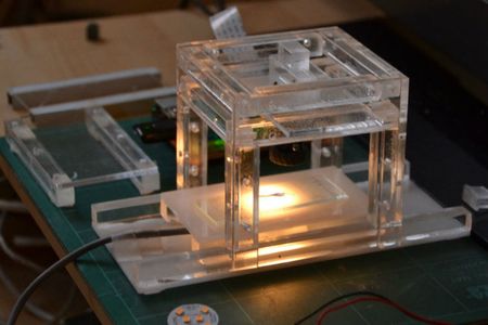
Step 3: Illumination; Reflected Light Vs. Transillumination Microscopy


The best way to illuminate your object will depend on the object to be analysed and what you like to see.
As such, the microscope is a reflected light microscope and you may use an external light source. If you like to perform transillumination microscopy, things are a bit more complicated.
For this prototype I was simply using a object tray with a opaque white plate, and placed a small 1.6 W 12 V LED lamp below it. Many 12 V LED lamps run on 9V as well, allowing to use a standard 9V block battery as a power source. To simplify handling, I placed a small switch between lamp and battery.
Other LEDs or light sources, e.g. COB LEDs (available from Banggood), are even smaller and give a more homogenous light distribution.The backlight LEDs from Adafruit might also be used for transillumination.
A similar constructs could be used for reflected light microscopy as well.
Step 4: Documentation and Plan; SVG-files
Here you find the original building plan (in German) and the according SVG-files.
Plate 1 was made from a 3 mm clear acrylic plate, plate 2 from a 3 mm white/opaque acrylic plate.
If you eliminate the holes in plate 1, the cutting price will drop significantly .
To view or modify the SVG-files you may use Inkscape, or a variety of other programs.
The comming version will be simpler to assemble, and probably be made of white acrylic. But you may choose from a wide variety of colors.
Please note: you may use this instructions for personal or educational purposes, both on your own risk.
The provided SVG files do not reflect the latest version of the project, I have not checked them for errors in deep detail, and they are just meant as a guideance for your own version.
I reserve myself the right to use the concept for commercial use and may offer instructions, building kits or assembled products, either by myself or a named third party.


Step 5: Current Developments


Over the last weeks, the concept has underwent a number of modifications and optimizations.
By now its all an ongoing process and I will present the system as soon as it has reached a reasonable and stable degree of improvement and has been validated by a third party.
The pictures may give you a bit of an idea about the current status. The current layout allows easy and rapid assembly, attachment of gears to move camera and object tray, a z-axis option, optimized illumination and more.
But by now, it is many options, but too little validated details.


