

Introduction: ATTiny84 + LCD + LM35 Temperature Sensor


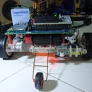

This is a simple temperature sensor built with a ATtiny84, LM35 and a 16x1 character LCD. It is made to run on 3 AA batteries or 4.5 volts. I made it as a project to learn how to port Arduino projects into smaller devices such as ATtiny84, ATtiny85 etc. Its also quite useful in various occasions too have a temperature sensor handy.
The basic concept of it working is it starts up, reads temperature (2 updates per second), displays it on the LCD and shuts down after 1 minute, The shutdown time can be extended by pressing the tact switch at the side of the box. Each press adds 60 seconds to the countdown timer and also displays how many minutes left before it shuts down.
Step 1: Preparing Parts and Materials.


This is the list of materials and parts I used to build this project:
ATtiny84A-PU PDIP14
LM35 Temperature sensor
Salvaged 16x1 character LCD module from a fax machine
Momentary tact switch
10K resistor
Female Header Pins
Copper clad board
Tools:
Soldering iron + solder
Arduino Uno R3 for testing purposes and code development
Breadboard
ISP programmer (Arduino ISP would do)
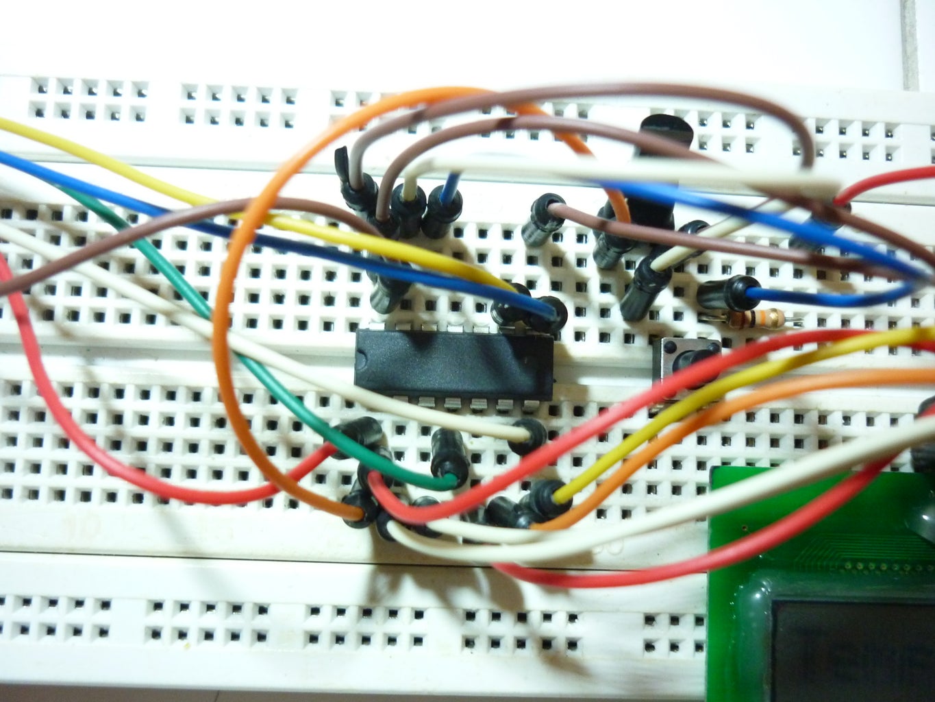
Step 2: Building Circuit and Testing


Initially this project was going to use ATtiny85 and a 74HC595 shift register but due to the problems with USI SPI i cant get them to work so I just switched to a ATtiny84 to replace them.
The circuit was initially built around the Arduino Uno during the code development period and then I changed the pins to suit the one I used on the Attiny84, which still works without any problem on the Uno.
The code for the project is included below: (updated with Fahrenheit and Kelvin mode)
#include <avr/sleep.h>
#include <LiquidCrystal.h>
LiquidCrystal lcd (10, 9, 8, 7, 6, 5);

byte degree[8] = {
  0b00000,
  0b11100,
  0b10100,
  0b11100,
  0b00000,
  0b00000,
  0b00000,
};
const int  buttonPin = 1;     // the pin that the pushbutton is attached to
const int tempPin = 0;
const long interval = 500;    // the delay in milliseconds for the temperature reading to update
unsigned long previousMillis = 0;
int buttonState;              // current state of the button
int lastButtonState;          // previous state of the button
float tempC = 0;
float tempF = 0;
float tempK = 0;
int reading = 0;
unsigned long pwrofftime = 600000; //initial time before powering down in milliseconds
int tempmode = 0;       //0 = celcius, 1 = fahrenheit, 2 = kelvin

void setup(){
  analogReference(INTERNAL);  //sets the reference voltage for Arduino's ADC to 1.1 volts
  pinMode(buttonPin, INPUT);
  lcd.begin(8, 2);
  lcd.createChar(8, degree);
  lcd.setCursor(0, 0);
  lcd.print("Hello");
  lcd.setCursor(0, 1);
  lcd.print("World!");
  delay(1000);
}

void loop(){
  buttonState = digitalRead(buttonPin);
  unsigned long currentMillis = millis();
  if(buttonState != lastButtonState) {
    if (buttonState == LOW) {
      lcd.clear();
      tempmode = tempmode + 1;
      if(tempmode > 2){
        tempmode = 0;
      }
      if(tempmode == 0){
        lcd.setCursor(0, 0);
        lcd.print("Celsius");
        lcd.setCursor(0, 1);
        lcd.print("Mode");
      }
      else if(tempmode == 1){
        lcd.setCursor(0, 0);
        lcd.print("Fahrenhe");
        lcd.setCursor(0, 1);
        lcd.print("it Mode");
      }
      else if (tempmode == 2){
        lcd.setCursor(0, 0);
        lcd.print("Kelvin");
        lcd.setCursor(0, 1);
        lcd.print("Mode");
      }
    }
    pwrofftime = pwrofftime + currentMillis;
    delay(500);
    lastButtonState = buttonState;
  }
if(currentMillis - previousMillis >= interval) {
    previousMillis = currentMillis;
    int reading = analogRead(tempPin);
    tempC = reading / 9.31;
    tempF = (9/5)*tempC + 32;
    tempK = tempC + 273.15;
    lcd.setCursor(0, 0);
    if(tempmode == 0){
      lcd.print("TempC:      ");
      lcd.setCursor(0, 1);
      lcd.print(tempC);
      lcd.write(8);
      lcd.print("C   ");
    }
    else if(tempmode == 1){
      lcd.print("TempF:      ");
      lcd.setCursor(0, 1);
      lcd.print(tempF);
      lcd.write(8);
      lcd.print("F   ");
    }
    else if(tempmode == 2){
      lcd.print("TempK:      ");
      lcd.setCursor(0, 1);
      lcd.print(tempK);
      lcd.write(8);
      lcd.print("K   ");
    }
  }
  if(pwrofftime < currentMillis){
    sleep();
  }
}


void sleep(){
  lcd.setCursor(0, 0);
  lcd.print("Powering");
  lcd.setCursor(0, 1);
  lcd.print(" Down...");
  delay(1000);
  lcd.setCursor(0, 0);
  lcd.print("Powered ");
  lcd.setCursor(0, 1);
  lcd.print(" Down.");
  set_sleep_mode(SLEEP_MODE_PWR_DOWN);
  sleep_enable();
  sleep_mode();
}
Attachments

Step 3: Programming the ATtiny84

To begin programming the ATtiny84 I start by loading the ArduinoISP sketch into my Arduino Uno, then I connected the respective pins of the Arduino into the ATtiny84 on a breadboard.
After preparing the required files for Arduino on ATtiny MCU's from https://code.google.com/p/arduino-tiny/, I burned the fuses for the ATtiny84 using avrdude included in the Arduino IDE.
To save power I used 1Mhz as the clock speed, so
In the Arduino IDE : Tools> Boards > ATtiny(internal 1Mhz clock)
Then click Burn Bootloader to burn the fuses into the ATtiny84 chip.
After the burning process ends (should be very quick) click Upload to compile and upload the software into the ATtiny84.
Step 4: Finishing Up (Pictures Too)


After everything's working on breadboard I moved them to the PCB I etched myself and soldered the parts together. I used a IC socket for the ATtiny84 so I can pull them out for reprogramming in the future.
The circuit is mounted on a 4 AA battery holder.
After everything is done I did some current draw tests with my multimeter and the circuit draws ~2 mA in active mode and ~0.6 mA in sleep mode. Next time I'll see i can drop the current draw more by using transistors or MOSFETs to switch the LCD and temperature sensor off when it goes to sleep.

Participated in the
Tech Contest

Participated in the
Microcontroller Contest


