

Introduction: ATtiny85 Two-Channel Lead Acid Battery Charger


Winter just arrived. The enemy of all batteries. Last year this was the season the auxiliary battery of my T3 VW camper bus bit the dust. This likely happened because I neglected to take care of it over the winter months during which the bus is typically parked in my garage. When the auxiliary battery is really dead dead, aka croaked, it is not only not working, but it also prevents the main battery used for starting/driving of the bus to be properly charged when driving. Not a good situation if you are somewhere out in the woods and eventually need a ride back to civilization. After almost getting stuck in the boonies, I decided to build a two-channel battery cycle charger that is supposed to keep both batteries happy and healthy for these winter months. You can see this project documented here.
The design, which is housed in perforated aluminum and wood, is based on an ATtiny85 microprocessor. For programming I used an Arduino as ISP and the Arduino programming environment. Connections to the batteries are made with cigarette lighter style connectors. Two analog inputs of the ATtiny85 are used to monitor the voltage of up to two batteries. Two digital outputs are used to switch charging of up to two connected batteries off and on. Two voltmeters display the voltages of the connected batteries and two LED indicators show the charging and connection state of the batteries. The device features a single 15V/5A power supply that, when two batteries are connected, charges either one or the other battery, while ensuring that neither battery drops below a predetermined voltage. Last but not least, there is an on/off switch.
To use the device you plug in one or two batteries and switch it on... in that particular order. The device will then detect any connected batteries, determine their charging state and charge them whenever needed. Keep your batteries plugged in over the winter and you are a happy camper with happy batteries when spring and summer come along.
Please let me know if you have any questions, comments, or suggestions.
P.S. A good complementary device is this battery tester by rlarios which is based on an ATtiny13. Great work rlarios.
Disclaimer:
Please note that lead acid batteries have a number of very significant hazards, including but not limited to electrical hazards, fire hazards, and chemical hazards. You can set a house on fire when charging a lead acid battery improperly. Soldering and dabbling with electronics involves another set of hazards. If you decide to recreate any parts of this instructable, you do it at your own risk. I will not accept any responsibility for your activities, good or bad, and can't be held accountable for your doings.
Let's build.
Step 1: Electrical Schematic

When I started with this project, I didn't know much about lead acid battery chargers and needed to inform myself first to make this project a success. So as usual, I googled until the cables started smoking.
I found many charger circuits that got close to my needs. You can find examples here or on this site. However, none of the devices I found could charge two batteries at the same time.
This charger I found very interesting, since it used a slick design with an IC555 as the main chip. The circuit was built to charge a single battery, using the IC555 as a comparator. Neat. I communicated with the author and started a dialogue on how to build a two battery design. Thanks to the author for his valued responses. Triggered by my questions he posted a blog that had the design I suggested for two batteries with some minor additions.
However, after thinking about it a bit, I concluded that even this design was not suitable for charging two batteries without limiting the charging current to half the current capacity of the power supply. For example, I had a 15 V/5 A power supply which was large enough to charge one battery at a time at 5 A. However, charging two batteries at 5 A would overload the supply. When charging two batteries, the voltage output of my particular supply would break down, the IC555 would lose power and the whole functionality of the device was shot. Not a good enough recipe.
The obvious workaround involved charging the batteries with smaller currents of or below 2.5 A. This would obviously increase the charging time at each battery which was not really that critical for my application since I was going to connect the battery charger for months at a time. To be honest, I had no idea how long the charging times would be. I decided it would be better to use a more intelligent circuit that would, when needed, only charge one battery at a time without letting the other battery drop below its low voltage threshold. In other words, if the low voltage threshold of the second battery is breached while charging the first battery, charging of the first battery is stopped and the second battery is charged instead; or vice versa.
Here I am presenting such a circuit. It uses an ATtiny85 as its brain. This IC is a small microprocessor, that has enough inputs and outputs available for the job and is fully programmable.
In the figure you see roughly from left to right:
+ Voltage dividers R1, R2, P1, to step down the battery voltages to below 5V levels: 16V => 5V, 1024 steps
+ ATtiny 85, left: analog inputs, right: digital outputs = High / Low = charging / not charging
+ Red and green LEDs with current limiting resistors R3; High signal = red LED on = charging, Low signal = green LED on = not charging
+ Optocoupler circuit: current limiting resistor R4 for internal LED. High signal switches optocoupler on => connection between pin 4 & 5 is created
+ R5 = pull up resistor
=> when optocoupler off, then +15V is at pin 5
=> when optocoupler is on, then GND is at pin 5
+ PNP Darlington transistor with base resistor R6, GND at R6 => Transistor open, +15V at R6 Transistor is closed
+ Reversed current protection diodes D1: Prevents current to flow back from the battery into the circuit.
+ Current limiting resistors R7: These depend on your batteries and power supply. I used 3x 1Ohm/25W resistors to start out. These limit the output current to maximal 5A. Note that the output current is significantly decreased by the internal resistor of the battery you are charging. I decided, since my goal was to maintain the battery charging state over weeks at a time, a high charging current wasn't quite that important. Please see step 13 for more explanation.
Step 2: Charging Method and High/Low Values

The picture shows the charging method that I chose for my battery charging. I drew the image to visualize how a charge discharge cycle theoretically should look like.
Lead acid batteries can be kept happy in a number of ways. This website, for example, or this one give good overviews about lead acid battery and their electrochemical reactions. One simple way is to keep the voltage of the battery between a “Low Voltage Limit” and a “High Voltage Limit”. This is called “cyclic charging” and the strategy I chose to pursue. Mainly, because it was easy to understand and didn't require any current controlling circuits, which can get a little tricky.
Choosing an Upper Voltage Limit
It is important to know that a lead acid battery can create hydrogen and oxygen in the same compartment when the battery is overcharged. When this is done for an extended time period an explosion hazard may be created. The gassing threshold for a lead acid cell is 2.4V/cell. This means, for a battery with a nominal voltage of 12V, i.e. a lead acid battery that has six cells in series, the gassing threshold is 14.4V. Also note that the typical output of an automotive alternator is 13.8-14.0V.
Based on this information I chose 14V as the upper Voltage limit to which the battery will be charged.
Choosing a Lower Voltage Limit
The open circuit potential of a lead acid battery at full charge and at full discharge are given as 2.1 and 1.95V/cell, respectively. I interpret these numbers to mean that a full 12V battery that is not charging has an open circuit potential of 12.6V, and an empty one has an open circuit potential of 11.7V, respectively. Any discharge that is more severe than full discharge can apparently limit the lifetime of your battery. Since I needed to maintain two batteries at the same time, but my charging strategy only charges one battery at a time, I wanted to have some buffer available that prevents total discharge at all times.
Therefore I decided to set the lower voltage threshold to 12V.
Step 3: Tools Needed for Electronic Circuit
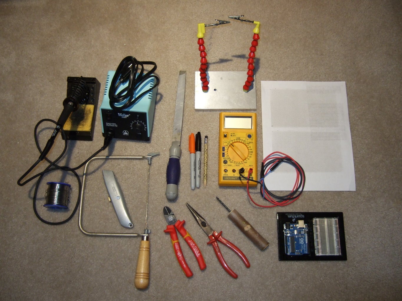
To create the circuit board on a strip board you need the following tools:
- Solder iron & solder for soldering electric components
- Hand saw to cut the board
- File, to deburr the board after cutting
- Cutting and bending pliers
- track interrupter tool (great instructable to make your own)
- Several waterproof markers of different color
- Third hand to hold stuff when soldering (this one is awesome, another good instructable)
- Voltmeter to test and troubleshoot
- Empty stripboard layout on paper; needed to transfer the schematic to the stripboard, done already for this built
- Arduino, needed later together with a breadboard or programming shield to program the ATtiny85
Step 4: Parts List for Electronic Circuit

1x, DC Power Supply, 15V/5A/75W, power supply, $23.65
2x, R1, Resistor 15kOhm/0.25W, sense voltage divider, ~$0.085
2x, R2, Resistor 5.6kOhm/0.25W, sense voltage divider, ~$0.085
4x, R3, Resistor 1kOhm/0.25W, LED current limiter, ~$0.085
2x, R4, Resistor ??Ohm/0.25W, Optocoupler LED current limiter, ~$0.085
2x, R5, Resistor ??Ohm/0.25W, pull up resistor, ~$0.085
2x, R6, Resistor 470Ohm/0.25W, base current limiter, link, ~$0.085
6x, R7, Resistor 1Ohm/25W, charging current limiter, 25W1D0, $1.41
2x, P1, Potentiometer 10kOhm/0.5W, calibration/scaling of voltage sense, Trimmer, 23 Turns, $1.57
2x, C1, Ceramic Capacitor 0.1uF/50V, noise filter, $0.105
2x, D1, Schottky Diode, 40V/8A, reverse current protection, $0.883
4x, 8-position DIP sockets, $0.12
2x, IC insulation kit for TO-220, $2.90 for 10x
2x Heat sink,
1x, IC1, ATtiny85, programmable microprocessor, ATtiny85-20PU, $1.29
2x, IC2, Optocoupler, control and charge circuit separator, Vishay SFH 600-2, $0.222
2x, IC3, Darlington Transistor, switching charge current on/off, TIP 147, $2.03
1x, IC4, Voltage Regulator, LM7805, regulate voltage to 5V for control circuit, KA7805AETU, $0.275
2x LED red, 5mm
2x LED green, 5mm
Additional parts needed to put the strip board together including the strip board, jumpers, and stand offs have been listed in one of my previous instructables.
Step 5: Stripboard Layout

The picture shows the electrical schematic from Step 2 transferred onto a stripboard. I prefer to use stripboards for circuits that I am building only once. The stripboards I use have copper traces in one direction of the board, in the picture this is the horizontal direction. Vertical directions are made using jumpers or components such as resistors.
In the figure:
- The black components are located on the top side of the board. Note that the copper side is the bottom side.
- Each red X marks a track interruption. At this location the track is interrupted by cutting/interrupting the track with a ~4mm drill bit.
- All blue markings are connections that I made at the underside of the board, i.e. the copperside. These blue traces need to be able to carry a current up to 5 A. I "reinforced" the current carrying capacity of these traces with copper wire. Please refer to the following step to see a picture.
- The blue bridge connection "jumpers" from trace 8 to trace 17, without being in contact to any of the traces in between. Again, please refer to the following step to see a picture.
- Dashed lines are outlines of components such as ICs or heat sinks.
Optional Parts
- LEDs: Small dots with numbers identify locations to where the LEDs are connected with cables. The LEDs are optional, but will help a lot to understand the charging status of the batteries and the functionality of the device.
- Voltmeter: The two voltmeters are also optional, but very useful. They show the actual voltage of the battery when charging or idling. The voltmeters are connected to the sense input of one battery and ground.
- Current Test Point: You can further add a test point to the charging circuit that allows you to measure the current while charging the battery. This is very useful for testing and fine tuning the device. For each battery you need a DPDT switch that can handle 15V DC at 5A, and a couple of banana panel connectors. In the lower right corner you can see the functionality of the switch. When the switch is engaged, the current is routed to the banana connectors which can be connected to an ampere meter. Connecting this way allows you to measure the actual charging current of your battery, which will help to select the inline resistor you may want to select (if any). Note that I did not realize this option in my build.
Step 6: Populating and Making Strip Board


a) Marking the component positions:
I double and triple checked everything. Then I marked the locations of all parts on the top side of the strip board. I used black dots for all parts, and red dots for the track interruptions.
b) Cutting out the board:
I took my handsaw and cut out the stripboard section that I needed for the build. I carefully cut from hole to hole, which is a fairly fast and easy process with a fine edged sharp handsaw. Subsequently, I deburred the edges carefully with a file, to avoid sharp edges and shorts. I inspected all edges and traces to ensure that no traces were shorted.
c) Drilling holes for standoffs:
I chose a 1/8” (3.125mm) drill to fasten the standoffs. The nylon screws were M3 (3mm) which makes for a nice fit. I widened four corner holes where I had no conflict with any components. I deburred and inspected the holes on the copper side to ensure I didn't create any shorts.
d) Attaching the standoffs:
I stuck the M3 nylon screws through the hole and hand tightened the standoffs on the board. As shown in the pictures, the board could now stand by itself and was ready to be populated with components.
e) Adding the track interruptions at the holes:
Next I took my fantastic DIY track cutter and put all the track interruptions that are located at holes into the board. During the process I stuck a wire every now and then through a marked hole to orient myself and to keep track of the correct locations. Beware that the layout shows everything from above, i.e. the non-copper side, but the interruptions are all put into the copper side. After I placed the interruptions, I used the multimeter to confirm proper track interruption at each hole. Better to be sure right away. It's much harder to fix a small mistake later.
f) Adding the first set of components:
I usually build up a board starting with the components of lowest height, to higher and higher components. That often has the advantage to keep a larger number of components in place to solder them all at the same time. I inserted the jumper wires into their positions, placed another piece of strip board on top and flipped both boards around. The wires could not fall out that way and I was able to solder all wires in one run.
I added the resistors, IC sockets, potentiometer, voltage regulator, and diodes in the same way.
g) Adding the transistors:
The transistors had connector legs that did not fit into the standard hole size of the strip board. I carefully measured the leg diameter and selected the appropriate drill. Using a drill press I widened the holes for the transistor legs. Next, I tested the track of the holes for shorts to neighbor tracks before I inserted the transistor into the holes and soldered it onto the board. Note that the heatsinks are connected to the transistors using contact paste and insulating kits.
h) Adding the second set of components:
I inserted four of the high power resistors into the board and soldered them vertically onto the board. Subsequently I placed the other two resistors across one pair each, twisted the wires of the resistors together, and soldered them. I carefully stripped the insulation from the LED wires I had pre-assembled, inserted them into their location and soldered them onto the board.
i) Establishing high current pathways:
Along all current pathways that carry the charging currents for one of the batteries (positive as well as negative) I added some thicker non-insulated copper wire. I bent the wire carefully to avoid shorts with other tracks, and made sure that all required connection points were soldered. Note in the picture the bridge I made for a short section of wire. This bridge is shallow enough to clear the height given by the stand-offs, but high enough to clear any contacts underneath.
Step 7: Materials and Tools Needed for Wooden Housing Part


Materials
Piece of scrap wood:
Minimum 300 mm wide x minimum 310 mm long x ~10 mm thick
Piece of scrap perforated aluminum:
Minimum 200 mm wide x minimum 500 mm long
For example: www.mcmaster.com, item# 9232T211, Lightweight Alloy 3003 Aluminum Perforated Sheet, 36" x 40", 0.1875" Hole Diameter, 51% Open Area, 0.05" Thick, $48.71
Finishing Nails
Wood glue
Cable glands
Epoxy
Small screw for assembly with aluminum part
Tools
Carpenter square
Ruler and pen
Circular saw
Drill press
Drill bits
Forstner drill bits
General Drill bits
Plunge Router
Router bits
Flush Trim Bit w/ Top & Bottom Mounted Bearing, 1/2" Shank, 3/4" LD, #8814, $27.00
Two Flute Straight Router bit, 1/2” diameter, 1/2” Shank, 1 1/2” length, #7777, $8.95
Clamps
Scrap wood with straight edges
Hammer
Center punch
Spongue Sander
Step 8: Building the Housing


Baseplate / x-y Dimensions
I arranged the power supply and finished strip board together on a table and measured their footprint. I added some extra space to accommodate the voltage indicators that mount in the panel and allow for easy access to all contact points. The resulting x-y dimensions for the baseplate of the box came out to be 300 mm x 180 mm.
Height / z Dimension
To determine the height I needed for the box, I measured the height of the tallest part inside the box, i.e. the height of the fully assembled strip board including the high power resistors. I added an additional 50 mm for space and 9 mm for the thickness of the baseboard. The resulting 109 mm was the height the front and back panels needed to be. Front and backpanel dimensions were thus 300 mm x 109 mm.
Front Panel Design
The front plate groups voltage indicators, LEDs, and cable outlet for each battery together. Battery 1 is placed on the left and battery 2 is placed on the right. In the middle is a simple on/off switch for the power supply and thus the entire charger. This switch also servers as a reset for restarting the ATtiny85 program.
You can find all the dimensions I used for my front panel in the first figure shown in this step. Please note that most panel mount parts are made for much thinner panels than my 9 mm thick wood panel. This means that most of the screws/threaded parts and also the LEDs were not long enough for my panel. To account for this I reduced the panel thickness wherever a part was penetrating the panel. I also recessed the area behind the voltage indicators to bring the display closer to the front of the panel. This allowed for better looks and readability, but required also some router work.
Front Panel Built
Operating a router close to the edge of a wooden board is awkward at best. For easier handling and better results I decided to machine the recessed areas and openings before I cut the wooden board to size.
I started by drawing the positions of the holes, cutouts, and recessed areas onto the board. With exception of the voltage indicators all panel mounted parts required blind holes for the recessed areas and through holes. I marked all of these locations and prepared them for drilling with a center punch.
The voltage indicators were a little trickier. The desired geometry was a rectangle with round edges and required the use of a router. I started off marking center positions for drilling 25.4 mm (1") holes into the opening. I placed the holes as far as possible from each other, while ensuring that the drill bit would stay inside the opening. With a center punch I marked these drilling locations as well.
Then I drilled all the blind holes using forstner drill bits, followed by the through holes using forstner or general drill bits. The diameter for the through hole, diameter for the blind hole, and depth required for the blind hole / recessed part were respectively:
- LED: ø 5.0 mm, ø 5.8 mm, 5 mm
- Switch: ø 6.2 mm, ø 15 mm, 6 mm
- Cable Glands Batteries: ø 15.0 mm, ø 24 mm, 6 mm
- Cable Gland Power Cord: ø 12.4 mm, ø 20 mm, 6 mm
The two holes for the voltmeter display area I drilled with 25.4 mm (1") forstner bits. Forstner bits allowed me to drill overlapping hole regions with ease. Do not use regular bits, or if you have to, use smaller diameter drills bits and make sure they do not overlap. To cut out the rest of the hole for the voltmeter display I used the router bit with the top and bottom mounted bearing for trimming the edges. This procedure required several steps. First I clamped wooden pieces with a straight edge to three edges of the marked cutout. These boards acted as guides for the bearing of the router. After routing out this section, I moved the guides to the missing section and completed the cutout. The rounded edges matched the diameter of the router. Same procedure on the second cutout.
I then swapped router bits to the two flute straight router bit, adjusted the router depth to cut away 6 mm of material, and measured the distance of the router bit edge to the router base plate. The latter is the distance a guide has to be placed to get a straight cut. I clamped straight edged boards as guides along the long sides of the holes in that exact distance. Then I routed the recessed area for the voltage displays, eyeballing the short sides. I tested the feel and appearance to make sure all looks good and fits.
Using a table saw, I finally cut out the panel plate, back plate, and base plate of the box with my table saw. Make sure you consider the width of your saw blade when cutting. The parts were ready to be glued together. To strengthen the bonds I decided to use finishing nails. It's best to use nails with a somewhat dull top for thin wooden boards. This prevents splitting of the wood. As shown in the pics, I hit the nails on the tip with a hammer a couple of times so that they were dull before I used them. Then I grabbed a couple of right angle clamps and some wood glue and glued the parts together. I reinforced the bond with the nails, let it dry and repeated the procedure with the other side.
After the glue was dried I painted the wooden assembly with black paint, for a classic look. I guess a hammerhead blue would have been nice too, but I happened to have black paint in the house.
Aluminum Cover
Last not least and unfortunately not documented in pictures, I cut out a piece of perforated aluminum that was 197 mm ((180 mm + (2 * 9 mm)) - 1 mm) wide and 516 mm (300 mm + (2 * 109 mm - 1 mm)) long. I subtracted 1 mm from some edges to avoid potential protruding metal that could create sharp edges. I cut the material on a bandsaw and bend it on a bending machine. You can also do this at home using straight edged boards, clamping devices, and a hammer, but it takes some practice to get nice straight edges.
Step 9: Assembling Everything


To assemble the battery charger, I placed the power supply into the predetermined position and marked the two hole locations for fastening the device. I selected a couple of short philips screws that would work in wood and determined their core diameter. I drilled two holes with the appropriate drill bit to avoid cracking the wood. Then I inserted the screws and fastened the power supply.
To provide power, I inserted an 18 AWG power cord through the most right cable gland into the box. The phase/hot wire of the cable was routed first to a power switch, then to the power supply. All other cables, i.e. neutral and ground, were directly connected to the power supply. The power switch, which was inserted and fastened to the front panel, was now able to switch the power supply on and off. Note that all exposed contacts were either insulated via shrink tubing or via a small plastic shield that sits above the terminal screws of the power supply.
Next I soldered the 15 V power supply outlet wires to the power input of the strip board. In the pictures these are the red and black cable. Again I ensure that all exposed connections were insulated with shrink tubing.
I moved the strip board to the position I liked it to be and fastened it to the base plate of the box using a two component epoxy glue.
I had way to much extra cable connecting the voltage indicators / monitors to the front panel. To shorten these cables, I opened the voltage monitors and recorded the polarity and locations the cables were fastened to. I unsoldered the cables, shortened them and reattached them. Then I closed the housing and confirmed functionality.
Next I carefully propped up the housing with the front panel pointing downward. I inserted the voltage monitors/displays in their locations and glued them to the front panel using again two component epoxy glue.
I had previously fed the battery cables to battery 1 and 2 through their appropriate holes and cable glands. Each set of battery cables consisted of two current leading wires, i.e. to the positive and negative terminal, and one set of sense cable that were soldered to the appropriate outlet/inlets on the strip board. The groups of cable for each battery I held together with short pieces of shrink tubing.
Both sets of cables were terminated at the cigarette lighter style plug in connectors. Routing the sense lines separately avoids voltage reading errors due to the resistance of the cable at higher current. Since the connectors have only two contacts, the sense cable does not avoid errors due to the contact resistance from the plug. However, I combine the two cable sets inside of the cigarette lighter connectors as shown in the pictures. To do so, I opened and disassembled the cigarette lighter connectors. Then I reassembled the case and carefully widened the opening for the cable to allow for both cable set to enter the connector. I stripped all cables to a relatively short length and soldered the negate terminal cable and the ground cable to the "side connector". I repeated the procedure with the positive cables by soldering them to a short piece of cable connected to the center connector. For safety I insulated the connections to the positive terminals with shrink tubing, before I carefully reassembled the connector, which was a little tricky but manageable.
Step 10: Software


Since I am not the most experienced programmer, I had to think a bit before I put this program together. The list I wanted the program to do was:
- Do not create a hazard or problem with 0, 1, or 2 batteries connected
- Detect on which channels a battery was connected at start up
- Keep all connected batteries above or equal to 12.0 V open circuit voltage
- Keep all connected batteries below or equal to 14.0 V when charging
I developed three flow charts that I used to write my program. These flow charts are shown in the picture section for your convenience.
Check Connected Batteries - Void Setup
Flow chart 1 represents the start up / void setup and is executed only once. The software associated with flow chart 1 checks if any batteries are connected by looking for a minimum voltage of 1.56 V to be detected at the battery sense line. Yes = a battery is connected. No = no battery is connected.
Depending on which channels batteries are connected a variable "Mode" is set that determines which charging routine will be executed.
Batt1 or Batt2 Connected - Main Loop = One Battery Connected
Flow chart 2 shows the strategy for charging one battery. The same strategy is used for charging either battery 1 or battery 2. The loop is continuously repeated. First the battery voltage is read. If the voltage is above or equal to a certain high value (14.0V) charging is stopped. If not it is checked if the value is below or equal a certain low value (12.0V). If so, charging is started. A software following this flow chart will keep one battery charged between the low and the high value.
Batt1 and Batt2 Connected - Main Loop = Two Batteries Connected
Flow chart 3 shows the strategy for charging two batteries. The loop is continuously repeated. First the all battery voltages are read. Then it checks if battery 1 just completed to be charged. If so (yes), it will stop the charging. If the answer is no, it will check if battery 2 just completed to be charged. If so (yes), it will stop the charging. If the answer is no, it will check if battery 1 needs to be charged urgently. If so (yes), it will start to charge battery 1. If the answer is no, it will check if battery 2 needs to be charged urgently. If so (yes), it will start to charge battery 2. If none of the batteries needs to be urgently charged, the software will check if battery 1 was being charged and still needs to be charged. If so (yes) continue to charge battery 1. If not, check if battery 2 was being charged and still needs to be charged. If so (yes) continue to charge battery 2.

Step 11: A Couple of Links for Programming the ATtiny85


Coming from the Arduino side of things it was at first a little awkward to get going with the ATtiny85. It's worth making the effort though, because the potential for reducing the footprint of your projects is huge. Here are some tips to get you started a little faster:
I found this website to be a good reference: http://www.kobakant.at/DIY/?p=3742
You may need a programming shield to program the ATtiny if you do it more than once. I found this tutorial to be very helpful when making one: http://www.forkrobotics.com/2012/04/run-arduino-code-on-an-attiny/#comment-281 , but I used it in combination with quick connect dip socket such as this one here: http://www.adafruit.com/products/382
Summarizing the steps to program ATtiny85 with 8MHz internal clock:
1. Connect Arduino to computer (Arduino Uno board with ATmega328).
2. Open Applications/Programming/Arduino 1.05
3. Upload "ArduinoISP" to Arduino by
a. selecting File/Examples/ArduinoISP
b. selecting Tools/Board/Arduino Duemilanove w/ATmega328 (select your board here)
c. uploading sketch with upload button
4. Attach the ATtiny programming shield by:
a. attaching extensions for the 2x 6pins
b. aligning pins 8-13 with Arduino board
c. aligning pins Vin-Reset with Arduino board
d. connect boards
e. attach yellow cable of programming shield to pin7 at arduino board
5. Secure ATtiny at top of quick connect dip switch (as close to switch handle as possible)
6. Select ATtiny by Tools/Board/ATtiny85 (internal 8MHz clock)
7. Select “Arduino as ISP“ by choosing Tools/Programmer/Arduino as ISP
8. Select "Burn Bootloader" by choosing Tools/Burn Bootloader
9. Open sketch to upload to ATtiny
10. Select ATtiny by Tools/Board/ATtiny85 (internal 8MHz clock)
11. Select “Arduino as ISP“ by choosing Tools/Programmer/Arduino as ISP
12. Press "upload sketch" button
13. Ignore the following error message:
a. avrdude: please define PAGEL and BS2 signals in the configuration file for part ATtiny85
b. avrdude: please define PAGEL and BS2 signals in the configuration file for part ATtiny85
Step 12: Fine Tuning
Calibrating the Voltage Sense Lines
The ATtiny85 can only handle voltage of up to 5V. Higher voltage may damage the microprocessor. The voltage values of the lead acid battery charging circuit will be between 12 - 14V and may even reach 15V, the maximum voltage of the power supply. To allow measuring these high voltages with the ATtiny85 a voltage divider was used as apparent from the electrical schematic shown earlier. For accurate sensing of the battery voltages, the following procedure needs to be performed:
Battery 1:
- Set an adjustable power supply to a voltage output of 16.0 V.
- Confirm the voltage output with a voltmeter.
- Connect the power supply output of 16.0 V to the battery sense line of battery 1 and ground (GND).
- With a voltmeter measure the voltage between ATtiny85 pin2 and ground.
- Calibrate the measured voltage to exactly 5.0 V by adjusting the potentiometer of the sense line of battery 1.
Battery 2:
- Set an adjustable power supply to a voltage output of 16.0 V.
- Confirm the voltage output with a voltmeter.
- Connect the power supply output of 16.0 V to the battery sense line of battery 2 and ground (GND).
- With a voltmeter measure the voltage between ATtiny85 pin3 and ground.
- Calibrate the measured voltage to exactly 5.0 V by adjusting the potentiometer of the sense line of battery 2.
Optimizing the Charging Current
The battery charger shown here was designed for long term operation. It is intended to keep two batteries charged over a period of up to six months. The maximum charging current for this application is relatively unimportant. It just needs to be large enough to replenish the charge of both batteries faster than their loss. The maximum possible charging current (I) of the circuit is defined by the ohmic load (R) on the circuit and the supplied voltage U, through Ohm's Law.
I = U / R
The ohmic load on each charging channel consists of the three load resistors R7, and the internal charging resistance of the battery, (Ri). If the charging resistance of the battery is very low, i.e. 0 Ohms, the maximum current output to the battery would be I = 15V / 3 Ohm = 5 A, aka the maximum current of the power supply. If a current larger than 5 A is drawn, the output voltage of the power supply may break down significantly and it can happen that the ATtiny stops to operate. In short, the high power load resistors (total 3 Ohm), ensure that the power supply cannot be overloaded.
In reality, assuming a fully functional battery, the charging resistance of the battery will be higher than 0 Ohms. Therefore you may encounter significantly lower maximum charging currents than 5 A in real life. In my case that was of no importance, I just needed to make sure the charging rates are slightly higher than the loss of charge. But it may be of interest to increase the charging current when you like to charge your battery rapidly, e.g. overnight instead of in 4 days or so.
I suggest the following procedure to optimize your charging current:
- Pick a warm or hot day to perform this test. Temperature reduces the internal resistance of your battery, which means higher ambient temperatures are the best conditions for this test. In addition, the lower the charge of the battery, the higher the current will be that is drawn from the charger.
- Connect an ammeter in series with your battery to the charging output. The ammeter needs to be able to handle at least 5 A.
- Start up the battery charger and record what the charging current Icharge is.
- Calculate the internal resistance Ri of the battery using Ohm's law.
Rtotal = 3x R7 + Ri = U/I = 15V / Icharge
Ri = (15V / Icharge) - 3x R7
- You'll achieve the maximum current of 5 A when Rtotal approaches 3 Ohm. Ri is fixed, so to maximize your charging current to 5 A, you need to reduce your load resistors so that the Rtotal is approaching 3 Ohm as close as possible: Ri + Rload >= 3 Ohm.
- After calculating the Rload you need, replace the 3x R7 with resistors of appropriate size and power rating.
Step 13: Modifications at the Vehicle (Optional)


For charging of the auxiliary battery and the engine starter battery of my VW bus I used cigarette lighter outlets. As shown in the pictures, I installed the outlet for the auxiliary battery right next to the battery in the battery compartment that is beneath the drivers seat. I selected appropriate screws, measured their core diameter, and marked the desired hole locations. I drilled a couple of holes and fastened the outlet with sheet metal type screws. Then I connected the cigarette lighter to the terminals of the auxiliary battery.
For charging the engine battery I intended to use a cigarette lighter outlet that already existed. This outlet was located below the passenger seat.
The first field test of the charger with my VW Bus showed that I could successfully charge the auxiliary battery of the camper, but not the engine battery. The 12V cigarette lighter outlet under the passenger seat was only operational when the ignition switch is engaged. Bummer.
As shown in the schematic, I worked around this matter by connecting a switch that enables a connection between the battery and the cigarette lighter outlet as shown in the schematic and the figure. I fastened this toggle switch (250V / 5A) under the passenger seat. However, remember that you may drain the engine battery if you use a device on this outlet and simultaneously leave this switch engaged when you are not charging the battery.
Subsequent tests were successful and the battery charger operated as intended. (Yeah.)
Step 14: Operating Manual

- Plug device into outlet.
- Connect battery cables to battery. (Make sure your cigarette lighter plug is directly connected to battery and not routed through ignition switch.)
- Switch on battery charger.
- A slow blinking sequence from red to green LED indicates that there is no battery detected on that channel.
- A permanent green light indicates a charged battery was detected and is being observed and maintained.
- A red light indicates that a discharged battery was detected and is being charged.
- Two voltage indicators will show if there are batteries detected. If no battery is detected the voltage indicator will toggle between a black screen and the power supply voltage in the rhythm of the blinking LEDs.
- Note that only one battery can be charged at one time with the system presented here, but up to two batteries can be kept happy.
- To detect additional batteries, connect to additional battery, switch the device off, and switch device on again.
Happy camping and tinkering everybody and please let me know if you found this instructable useful.


