

Introduction: AVR Programming With Arduino, AVRdude and AVR-gcc
AVR is a common, inexpensive type of micro-controller that may seem intimidating to work with, but don't fret! Once you have the tools set up and basic knowledge they can become not only useful, but essential to new project ideas that you dream up!
This tutorial aims to accomplish a few tasks
- Explain what an AVR chip is and why it is useful
- Provide detailed directions to set up an Arduino as an ISP programmer
- Provide a simple example project with code explained using the avr-gcc compiler and avrdude to install the program, rather than the Arduino IDE
To complete this entire tutorial, you need:
- ATTiny85 (Other versions will work as well, but will not be explained in detail)
- Arduino Uno (Other versions will work as well, but will not be explained in detail)
- A computer that can interface with the Arduino
- 5 Resistors and 5 LEDs
Please let me know any questions or problems that you have in the comments and I will try to answer them promptly!
Step 1: What Is AVR and Why Should I Care?
AVR is a micro-controller that can be used to direct the flow of electricity using software. It can be used to toggle devices, control them using Pulse-Width-Modulation, read values from sensors, and process that data to interact with its environment.
In addition, the AVR chips are very small. It is the chip that controls the Arduino.
For example, the ATMega328 is just under one square centimeter in size, yet contains 23 IO pins. It also only requires 1.8-5.5V to operate.
This can help you shrink down your Arduino projects to create wearable tech or smaller, more elegant robots.
Step 2: The Programmer Hardware
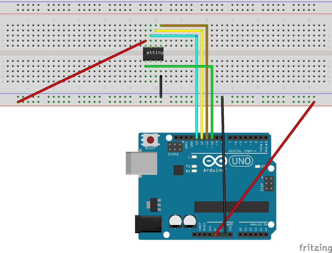
AVR chips can be programmed using a variety of hardware from a simple serial cable to a dedicated AVR programmer and development station.
While each of these methods has it's own benefits and drawbacks, I will focus on using an Arduino.
The Arduino is a large micro-controller prototyping platform. Arduino Uno has its IO pins broken out with headers attached. It is fully contained with all the needed parts to run the on board micro-controller such as a crystal and power supply regulation. It also has its own IDE and programming language that is quite similar to C. Using a program, it can be used to flash new software onto AVR chips.
The IDE includes a program called ArduinoISP that is supposed to do just that. Unfortunately, it is very finicky and rarely works with some models of Arduino. A variant on the program made by Adafruit that works more consistently can be found at this location.
If you are using Arduino Uno, then I recommend the latter program as I had much trouble with the official one.
Step 3: The Programming
An AVR chip can be programmed in various different ways.
- Install the Arduino Bootloader to use the IDE and language
- Use assembly. Though this may be very difficult to read and write, it can be very efficient.
- Use Atmel's official IDE Atmel Studio, but it is only available on Windows, not Linux or Mac
- Create program in your favorite C or text editor then compile and flash using avr-gcc and avrdude.
This offers a nice compromise between readability and efficiency as well as working on all platforms.
I will detail the fourth and final option.
Many editors will work for this as you will be simply writing a C program: Eclipse, notepad++, vi, as well as many more.
Please download the attached led_flash.c file and makefile.
I used an ATTiny 85 for this project.
I will first explain the code.
The first line of code is:
#include <avr/io.h>
This imports the constants relating to your AVR chip into the program. When you compile the program, you must specify the type of AVR chip that you use.
The next import:
#include <util/delay.h>
This includes the function to pause the chip during the loop.
Next comes some definitions:
#define shift_light_up(port) port << 1
#define shift_light_down(port) port >> 1
Defines macros to shift the light up and down the chain by one step.
#define register_set_output(register) register = 0b11111111
#define enable_first_light(port) port = 0b00000001
Defines macros to set an entire register to output and to enable the first light.
These definitions essentially create macros so that we do not need to use the code at the end later. It can allow the code to be much more readable than before.
Setting the register to all 1's in binary causes all of the pins to be an output, rather than input.
The port then sets the value of the pin to high or low.
port << 1 shifts the enabled pin by 1 place. port >> 1 moves it in the opposite direction.
boolean is_last_pin(uint8_t *port){
	if((*port & 0b00010000) > 0)
 		return true;
	else return false;
}

boolean is_first_pin(uint8_t *port){
	if((*port & 0b00000001) > 0)
		return true;
	else return true;
}
Two functions that allow the easy test of if the first or last pins are used by the lights currently.
Again, this makes the later code more readable.
int main (void){
	register_set_output(DDRB);	// Set it all to output
	enable_first_light(PORTB);	// Set the first light to on
	boolean up = true;
	while(true){
		_delay_ms(100);	// Dependent on the chip's clock speed, speed must be set

		if(is_first_pin(&PORTB) == true)	 //check if it is at the start
			up = true;
		else if(is_last_pin(&PORTB) == true) // check if it is at the end
			up = false;

		if(up == true)
			PORTB = shift_light_up(PORTB); // Shift our light up
		else
			PORTB = shift_light_down(PORTB);	 // Shift our light down
	}
}
This is the main portion of our function. The function int main(void) is called when the chip starts up. We first enable the register B to be all outputs. Then we set the first light to on and declare a boolean that remembers which direction to go. Each loop first delays for .2 second, then checks if the direction needs to change. It finally shifts the light in the given direction and repeats the loop.
That's it! the final program is a bit abstracted to allow it to be very easily readable.
Up Next: The makefile to automate the compiling and flashing process
Attachments

Step 4: The Makefile
Make is used to automate the process of building a program. you can setup a makefile to allow the entire process to be one command, "make program".
Using make creates macros to easily run a collection of commands relating to building a project.
The first command is the one called by default, so it may be useful to have a help macro first.
help:
	@echo 'Help details:'
	@echo 'hex: compile hex file'
	@echo 'flash: install hex file'
	@echo 'program: compile hex and install'
This always reminds you how you have the program set up instead of needing to look through your code if you forget.
The next part of this makefile is hex.
hex:
	avr-gcc -Os -DF_CPU=8000000 -mmcu=attiny85 -c led_flash.c
	avr-gcc -DF_CPU=8000000 -mmcu=attiny85 -o led_flash.elf led_flash.o
	avr-objcopy -O ihex led_flash.elf led_flash.hex
	rm led_flash.o
	rm led_flash.elf
This does the entire process to compile the chip. The process to compile a program for AVR is a bit difficult and long but this portion prevents you from needing to remember every portion of the process. The most important portions of this compiling process to remember is the --mmcu=attiny85 and the led_flash. These will need to be changed depending on your own project. If you are using a different avr chip, simply change attiny85 to the type that you use. If your file is not called led_flash.c, then change all the instances of led_flash with the file name.
Finally, the DF_CPU=8000000 defines the clock speed in the micro-controller. Many items such as delays will not work properly unless you set this to the correct value. If you use a different chip, or modify the speed in any way, please consult the datasheet for your AVR chip.
flash:
	avrdude -c arduino -p attiny85 -P /dev/tty.usbmodemfd121 -U flash:w:led_flash.hex
This installs the program onto the AVR chip. Please pay attention to:
-c arduino -p attiny85 -P /dev/tty.usbmodemfd121
This sets the type of pro
Step 5: Flashing and Compiling
Now that you have the makefile setup as well as the programming hardware setup, simply type
make program
This will compile the code and install the program on the AVR.
Congratulation! Only one more step, putting the chip in the actual circuit.
Step 6: The Final Circuit
The final circuit uses many resistors and LEDs, but is very simple to build.
Simply connect 5V+ to the VCC pin, Ground to GND, and the IO pins to a row of LEDs
Solder the circuit to a protoboard and build a fun container to show off your new skills to your friends and colleagues.
Step 7: Additional Resources
There are many places that you can find resources on programming AVR chips.
Atmel's Website can give you the data sheets for your specific chips:
The homepage for AVR Libc can give documentation on the avr specific libraries:
http://www.nongnu.org/avr-libc/
The gnu wiki on avr-gcc:
http://gcc.gnu.org/wiki/avr-gcc
AVRfreaks, A community around the avr chips:
A demo project from nongnu:
http://www.nongnu.org/avr-libc/user-manual/group__demo__project.html

Participated in the
Arduino Contest

Participated in the
Full Spectrum Laser Contest


