

Introduction: Adil Controller, Arduino Based Wireless Controller


More by the author:


About: I'm a Computer Science and IT teacher. I teach a university students how to be a professional programmers and to deal with new technologies in turn of productivity. My hobbies is ROBOTS & TECHNOLOGIES stuff. …
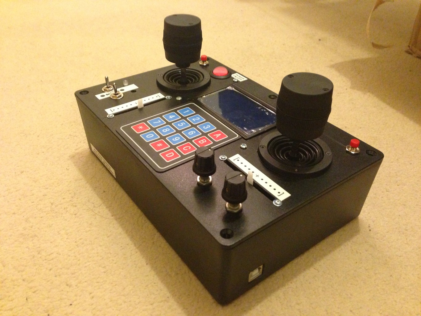
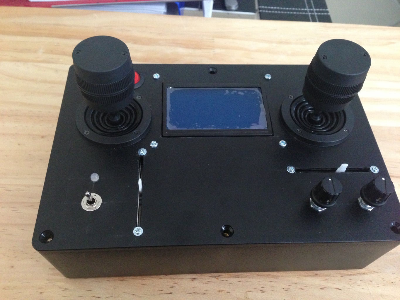
A new project of multipurpose remote controller. It will be used to control different robot models including a customised quadcopter. It is based on the ArduinoMega2560 microcontroller. Side-to-side with a 1200m range RF module for far distance connectivity with another RF module.
This is an open source controller. It's capability to handle over 13x9 channels in use for one person (i.e. over 117). So, it can control more than one robot at the same time just with an easy adjustment.
Also, you can add more channels by attaching a Wii nunchuck remote controller. That will add a motion sensing (gyro and accelerometer) and more.
P.S.
This idea was inspired by:
https://www.youtube.com/watch?v=n9BuDU_II5Q
(Please subscribe to his channel for cool ideas)
Attachments

Step 1: Gathering Tools and Parts
First of all, you will need some handy tools and skills to build this project.
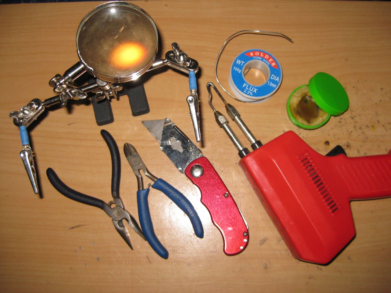
Tools are required:
- Drill + some bits including hole bit.
- A sharp knife.
- Solder iron.
- Pliers.
- Screwdriver.
- Helping hands.
- Wire stripper.
- A hole saw (here).
- Drawing compass.
- Digital Calliper, it is quite helpful (here).
- Labelling machine (optional).
- Tweezer(optional).
Parts are required:
- Wires (different colours).
- Rainbow ribbon cable (here).
- PCI board and/or breadboard.
- 2x Arduino prototype boards.
- Arduino Mega2560.
- An RF APC220/230 module. I'm using this one, but you can go with xBee modules.
- 4 lines LCD (I'm using this one because I can program it over digital pins).
- PC Screw (here). I use it for holding-in the Arduino and other boards.
- A set of bolts and nuts (here).
- A Multi-Purpose plastic box (here).
- 2x 10kΩ linear potentiometer (here).
- 2x 10kΩ log potentiometer (here).
- ON-OFF-ON toggle switch (here).
- A rocker switch with an LED. Used as the remote power switch (here).
- 3x push switch (here).
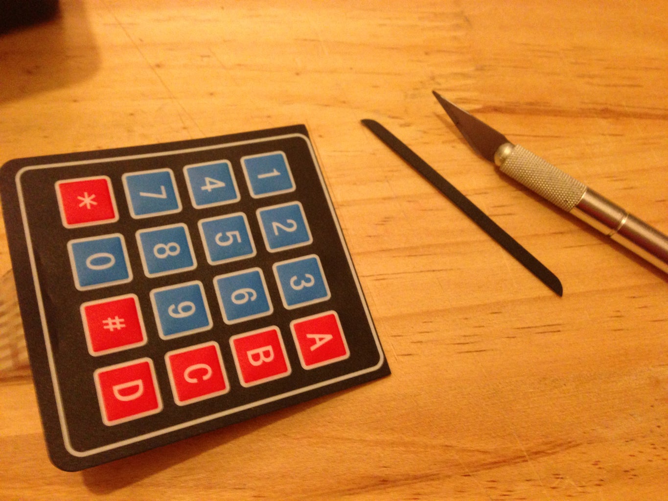
- 16 keys keypad (here).
- 2x rocker joystick (here).
- 2x RGB LED.
- Jumper wires.
- Resisters.
- A wii nunchuck remote.
- Wii nunchuck connector socket like this one here. I got mine from a non-used WiiMote by dis-solder it.
I hope I'm not missing something. If so, I will mention it later in next steps.
P.S. in this project I used 3 axis joystick, which has a three pots inside. They represents the YAW, PITCH and ROLL. Where you can move it up-down, left-right and rotate the top to left-right.
Tools are required:
- Drill + some bits including hole bit.
- A sharp knife.
- Solder iron.
- Pliers.
- Screwdriver.
- Helping hands.
- Wire stripper.
- A hole saw (here).
- Drawing compass.
- Digital Calliper, it is quite helpful (here).
- Labelling machine (optional).
- Tweezer(optional).
Parts are required:
- Wires (different colours).
- Rainbow ribbon cable (here).
- PCI board and/or breadboard.
- 2x Arduino prototype boards.
- Arduino Mega2560.
- An RF APC220/230 module. I'm using this one, but you can go with xBee modules.
- 4 lines LCD (I'm using this one because I can program it over digital pins).
- PC Screw (here). I use it for holding-in the Arduino and other boards.
- A set of bolts and nuts (here).
- A Multi-Purpose plastic box (here).
- 2x 10kΩ linear potentiometer (here).
- 2x 10kΩ log potentiometer (here).
- ON-OFF-ON toggle switch (here).
- A rocker switch with an LED. Used as the remote power switch (here).
- 3x push switch (here).
- 16 keys keypad (here).
- 2x rocker joystick (here).
- 2x RGB LED.
- Jumper wires.
- Resisters.
- A wii nunchuck remote.
- Wii nunchuck connector socket like this one here. I got mine from a non-used WiiMote by dis-solder it.
I hope I'm not missing something. If so, I will mention it later in next steps.
P.S. in this project I used 3 axis joystick, which has a three pots inside. They represents the YAW, PITCH and ROLL. Where you can move it up-down, left-right and rotate the top to left-right.
Step 2: Getting Started
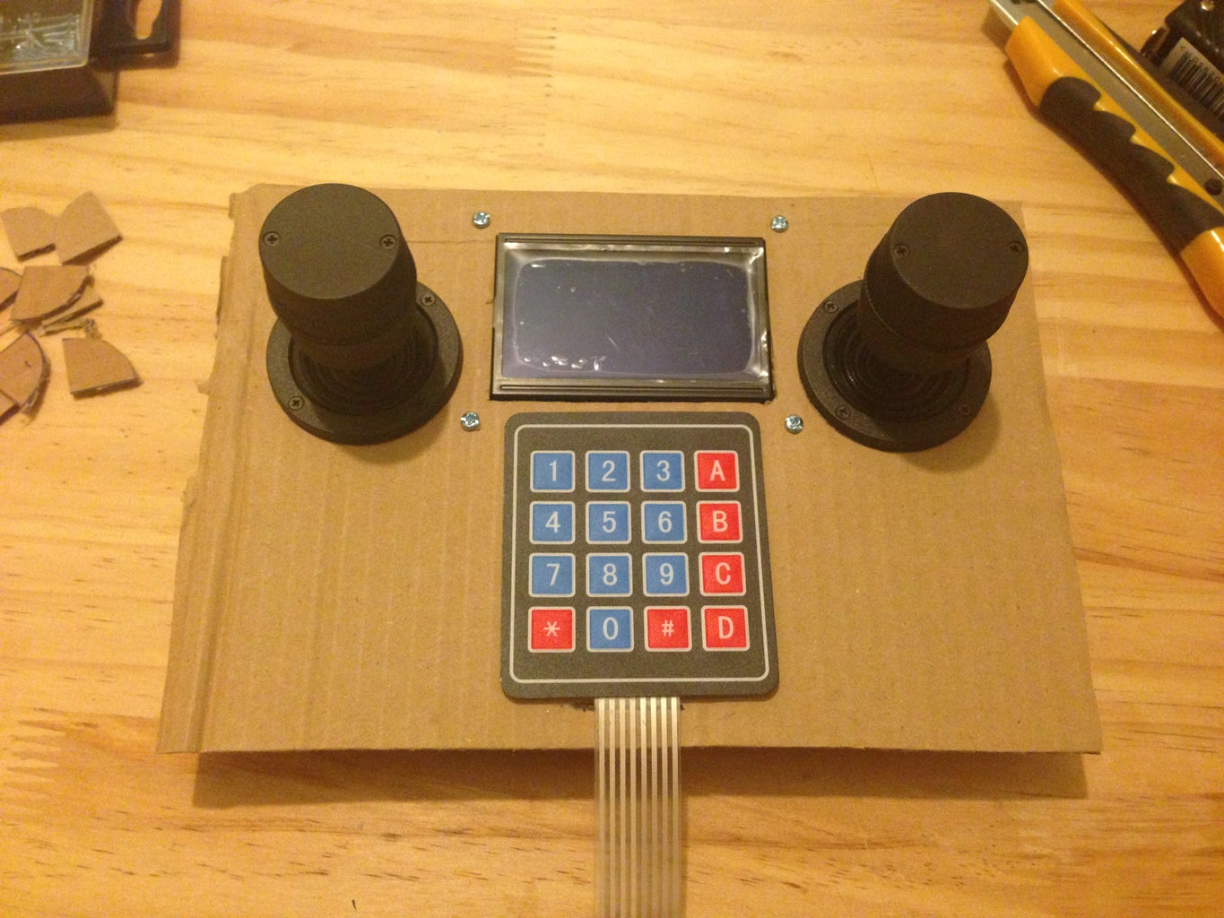

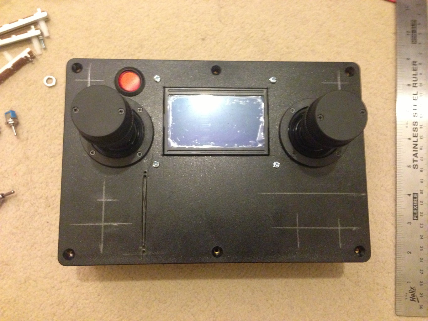
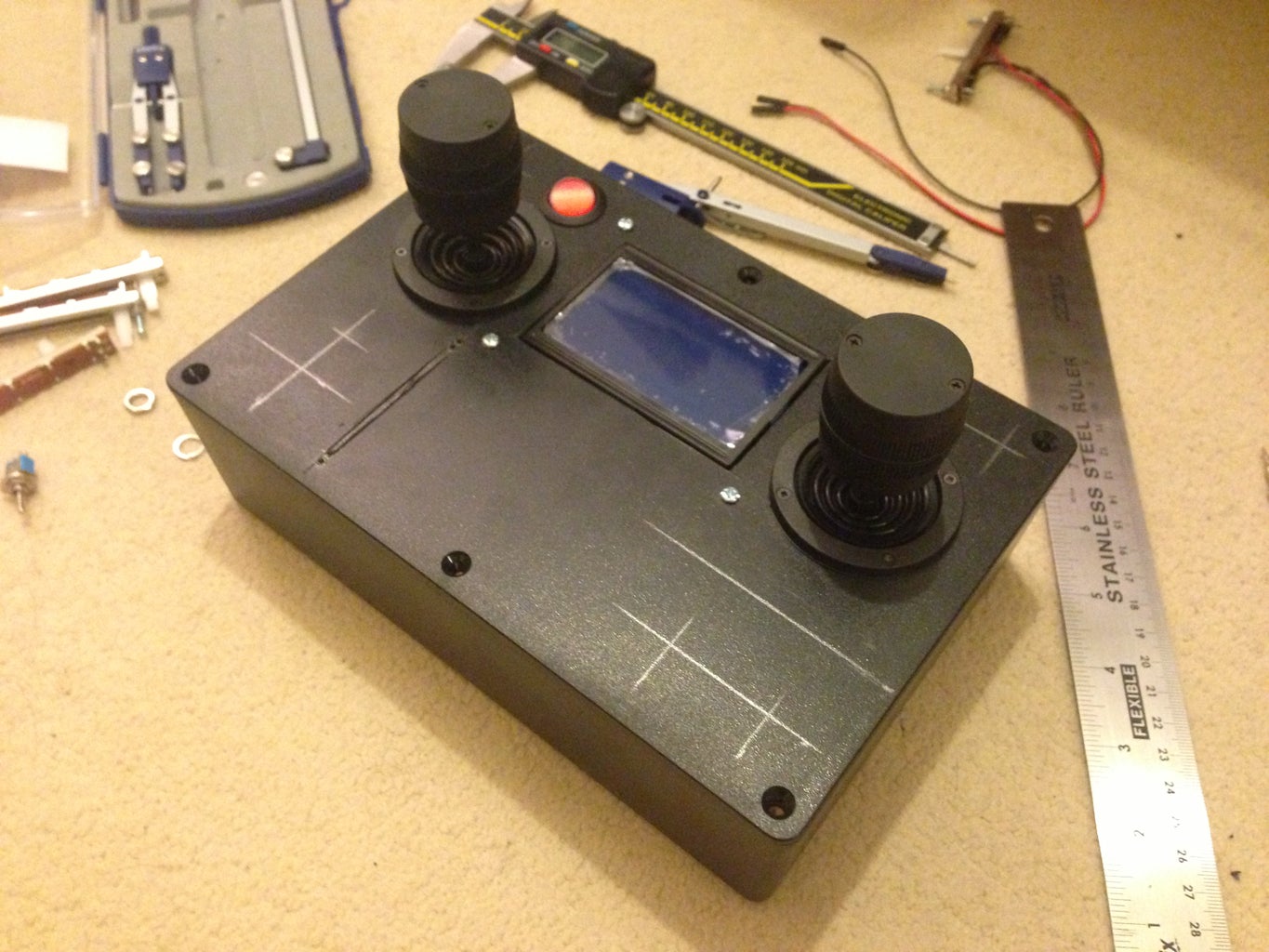
As a beginning, I needed to find the right plastic box for this project. So, I started by putting the large parts in together. In this case I had put the LCD, keypad and joysticks side to side. Then, I placed them into a cartoon board as this was easy for me to take measurements and do any necessary changes as I needed.
I searched the web for a local store where I can find this box in. The reason is because I wonted to hold the box in my hand for real to check if it fits nice and is comfy in hands or not.
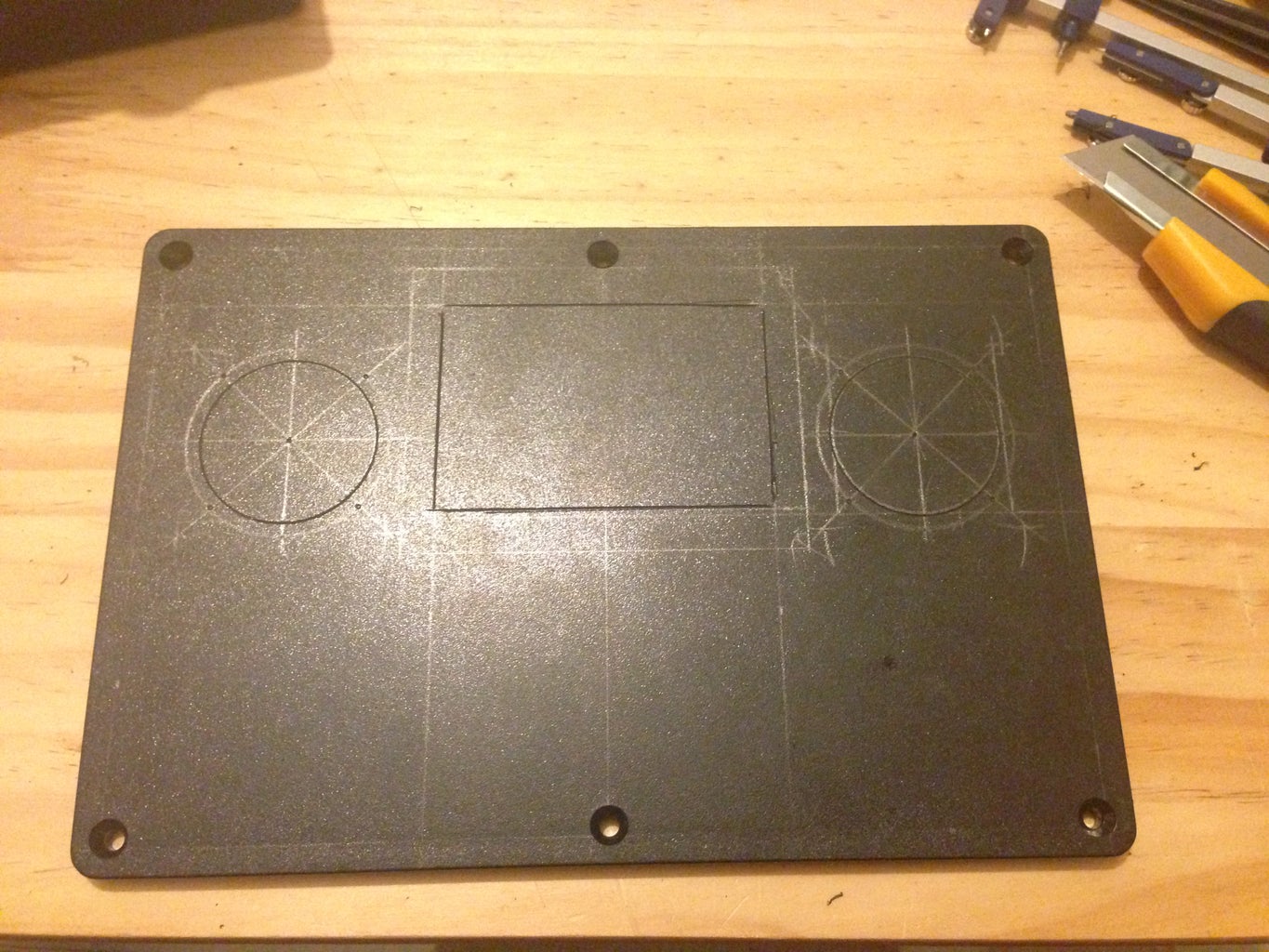
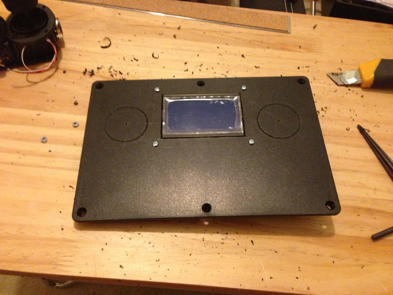
After that, I transferred the measurement from the cartoon board into the plastic box lid, like in the picture.
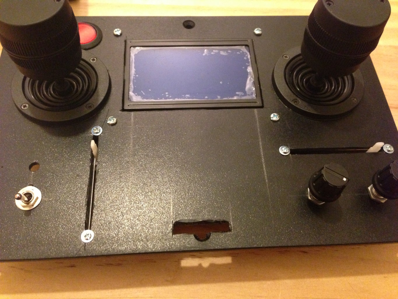
Because I didn't have a drill, so I made all the holes with a sharp knife. Yeah it took from me forever to finish them up. Then I placed the joysticks and the LCD screen in place first, but not the keypad yet.
I searched the web for a local store where I can find this box in. The reason is because I wonted to hold the box in my hand for real to check if it fits nice and is comfy in hands or not.
After that, I transferred the measurement from the cartoon board into the plastic box lid, like in the picture.
Because I didn't have a drill, so I made all the holes with a sharp knife. Yeah it took from me forever to finish them up. Then I placed the joysticks and the LCD screen in place first, but not the keypad yet.
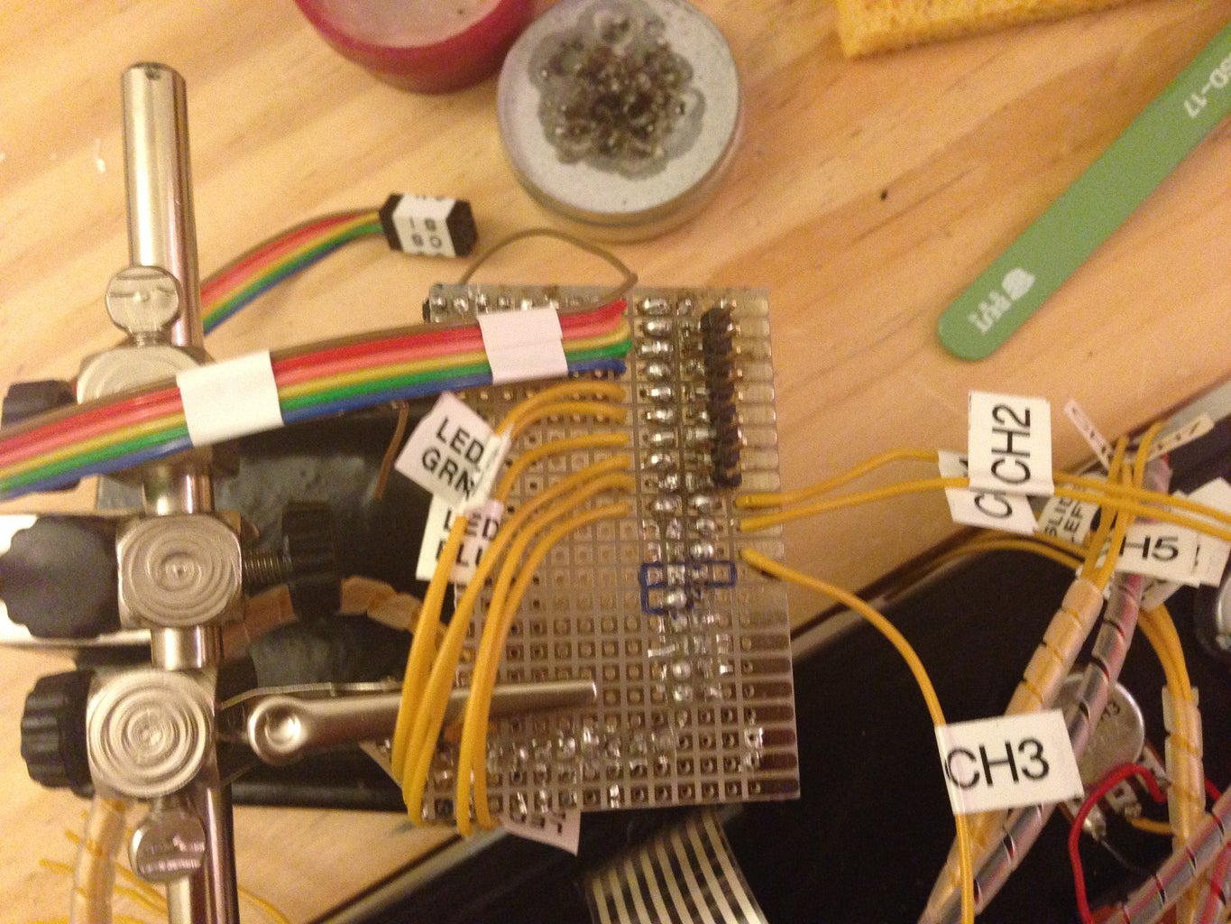
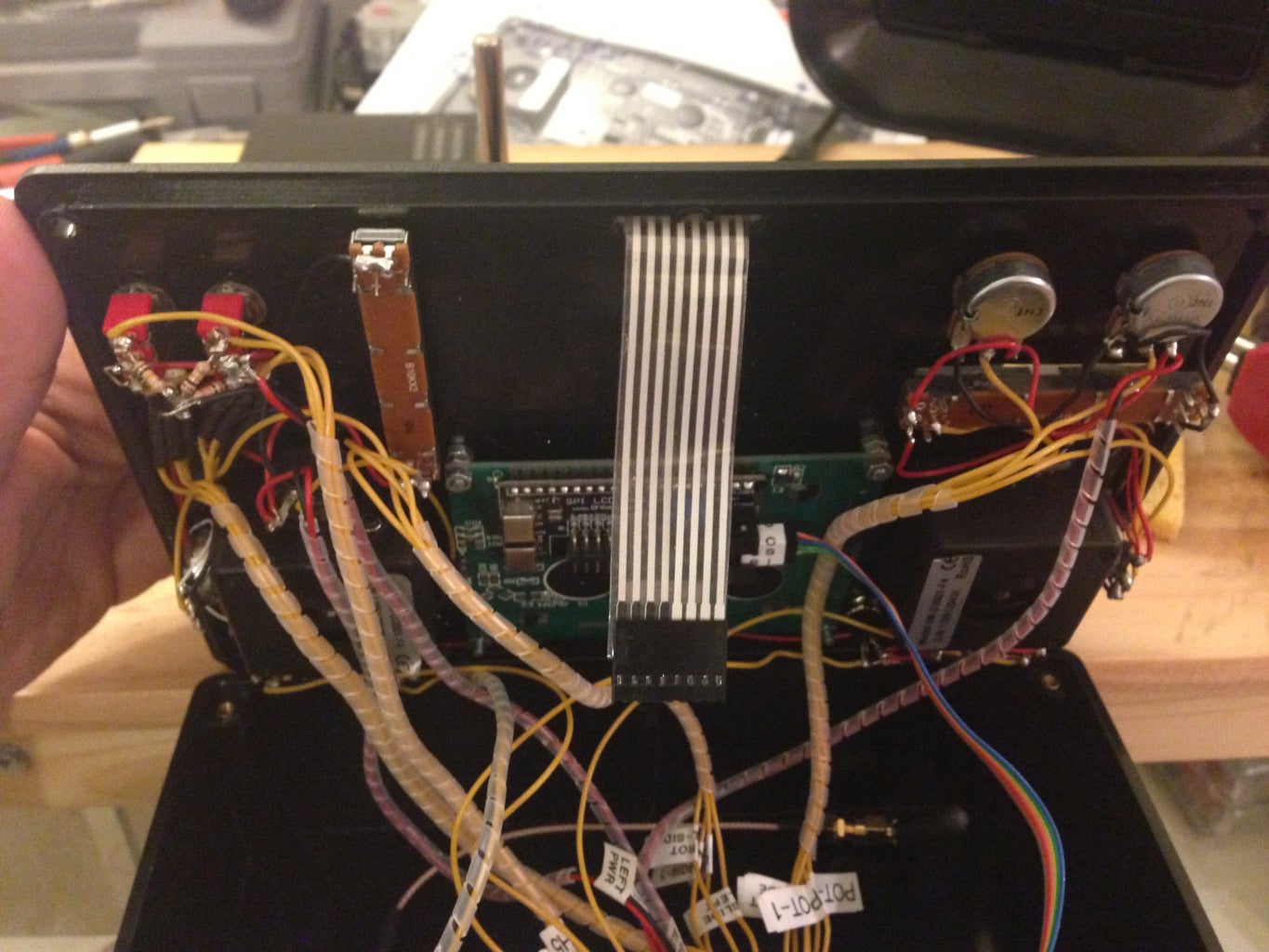
Step 3: Placing Switches and Potentiometers
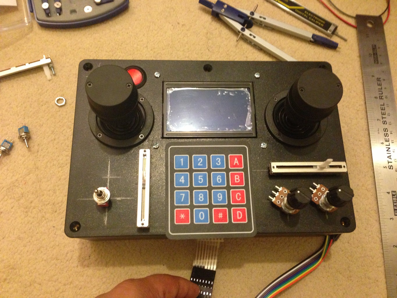


Now it is a good time to draw the lines where all the other switches must be placed.
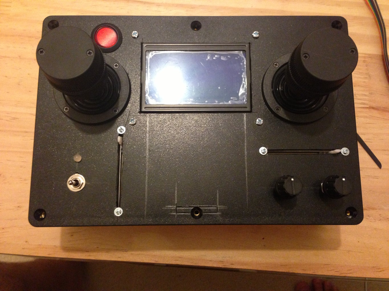
I first start with the power switch. It has to be in a place where it is impossible to be switch off by mistake. Also it should be sighted because it has an LED indicator in it. Where I will explain about this later.
However, I used the compass here to make all the pencil marks. It is easy to use the compass specially when transferring makes on both sides of the box.
The last part was the keypad. I had to get ride of one screw in the box because it was in the way where the ribbon cable has to be placed. So I mad a slot on the lid as you see in the pictures. Also, I had to trim the keypad a little bit so it can snuggle in its place correctly.
P.S. later I installed another push button and toggle switch. That because I found more room on the Arduino Mega which allows for having extra channels. See the last picture.
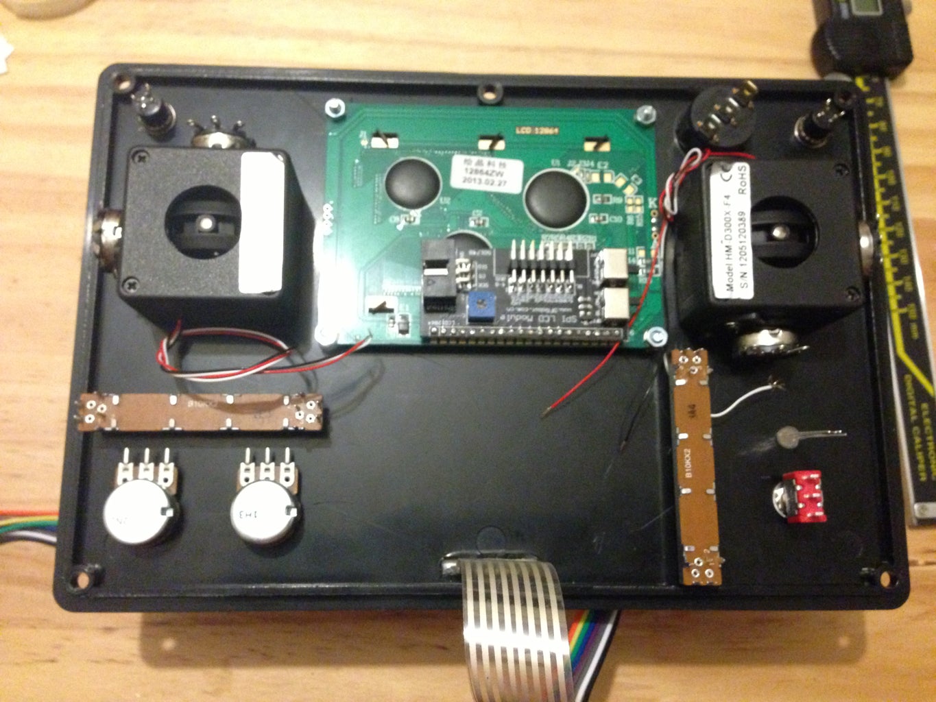
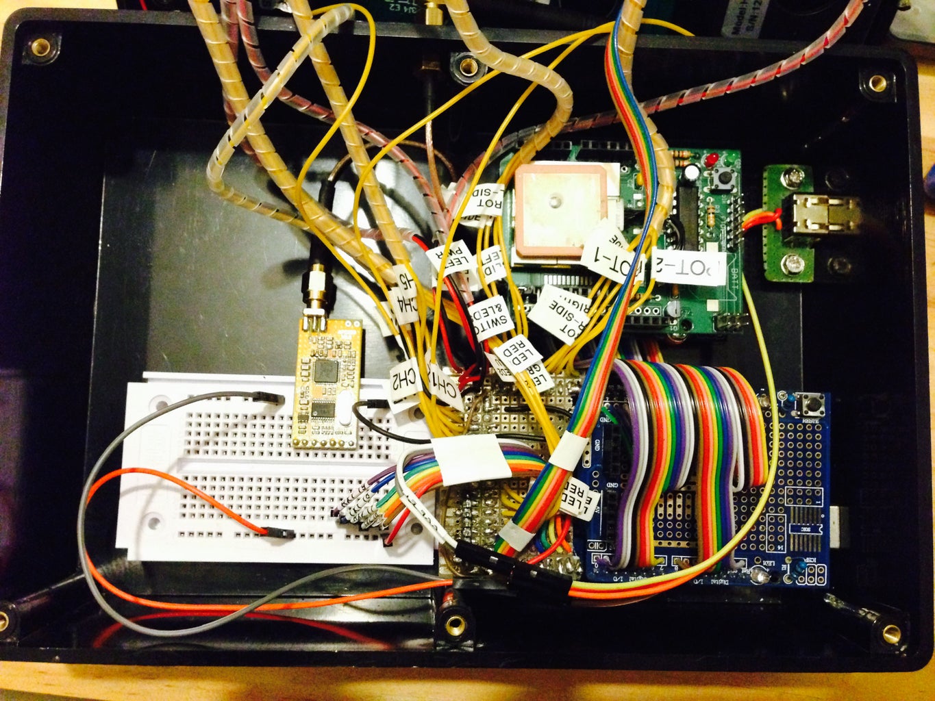
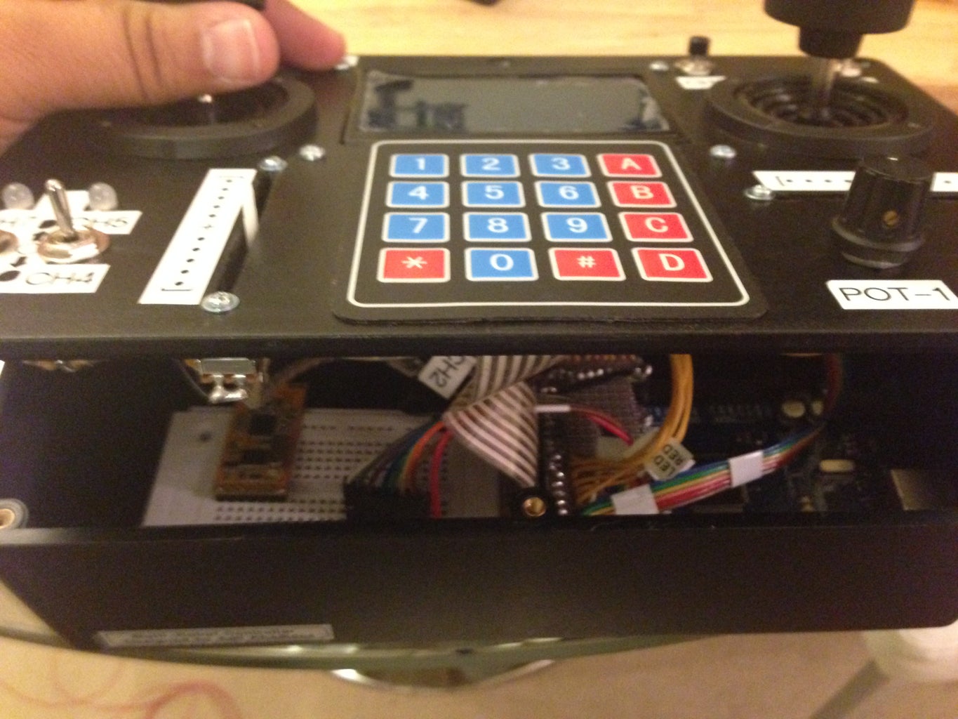
Step 4: Placing the Arduino Mega and the Other Boards

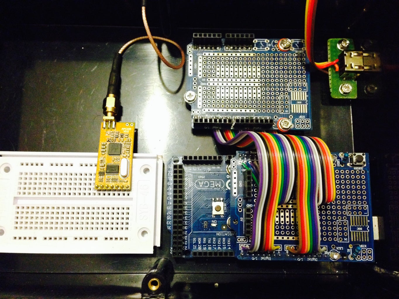
This was an easy step. All what you have to do is finding where the Arduino must be placed inside the box.
I found that the easy to access location is the right corner at the bottom. I also included breadboard next to the Arduino board for more extensions for an extra uses. These extensions are mostly the communication pins, serial 1, 2 and 3. In addition to SDA (pin 20) and SCL (pin 21). some of these communication ports are going to be used with the Wii nunchuck remote. Also it will be used with EEPROM module for extending the Arduino memory and adding a clock module as well.
In the first picture you can see the wireless module I used (APC220). I also included an antenna extension cable so to stick the antenna outside the box (I didn't mentioned this in the list as this could be an optional part).
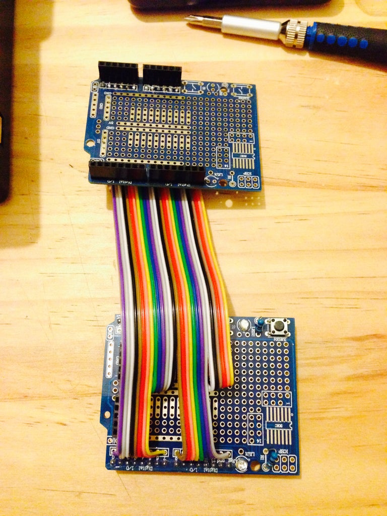
However, later I installed an extension board for Arduino as in the next picture. This is due two reasons:
1. I didn't have enough space for another shield to be placed on top of the Arduino board.
2. Also, I found its quite important not to place all the shields on top of the Arduino board because it will hit the components in the lid. So There was enough space underneath the LCD to where I placed the extension board.
For this Arduino extension boards, I used two Arduino UNO prototype shield, then I removed the pins from one of them and I removed the headers from the other board. After that, I used about 10cm long ribbon cable (28 wires) and solder them as corresponding to each other on both boards.
You may not need for this extension board if you already make enough room for other shields to be placed on top of the Arduino.
Then, I added the Wii nunchuck socket in place next to the Arduino. You can find a lot of schematics about how to wire the right pins on this socket in google. OR to make it easy, follow the structure in this instructable.
P.S. I used the PC nuts and bolts to hold all the boards to the bottom of the box.
I found that the easy to access location is the right corner at the bottom. I also included breadboard next to the Arduino board for more extensions for an extra uses. These extensions are mostly the communication pins, serial 1, 2 and 3. In addition to SDA (pin 20) and SCL (pin 21). some of these communication ports are going to be used with the Wii nunchuck remote. Also it will be used with EEPROM module for extending the Arduino memory and adding a clock module as well.
In the first picture you can see the wireless module I used (APC220). I also included an antenna extension cable so to stick the antenna outside the box (I didn't mentioned this in the list as this could be an optional part).
However, later I installed an extension board for Arduino as in the next picture. This is due two reasons:
1. I didn't have enough space for another shield to be placed on top of the Arduino board.
2. Also, I found its quite important not to place all the shields on top of the Arduino board because it will hit the components in the lid. So There was enough space underneath the LCD to where I placed the extension board.
For this Arduino extension boards, I used two Arduino UNO prototype shield, then I removed the pins from one of them and I removed the headers from the other board. After that, I used about 10cm long ribbon cable (28 wires) and solder them as corresponding to each other on both boards.
You may not need for this extension board if you already make enough room for other shields to be placed on top of the Arduino.
Then, I added the Wii nunchuck socket in place next to the Arduino. You can find a lot of schematics about how to wire the right pins on this socket in google. OR to make it easy, follow the structure in this instructable.
P.S. I used the PC nuts and bolts to hold all the boards to the bottom of the box.
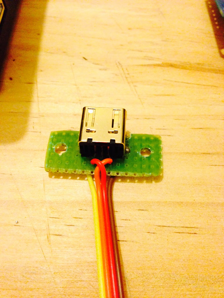
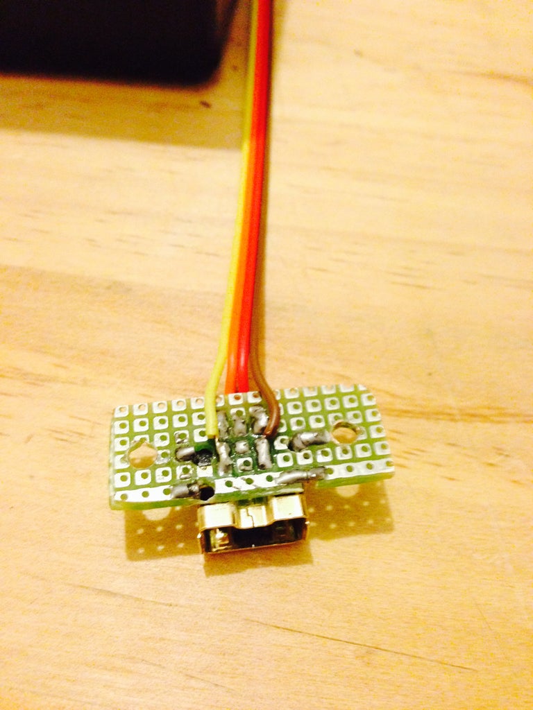
Step 5: Soldering, Wiring and Finishing Up

This is the final step, which it requires a lot of patience.
Unfortunately I don't have enough pictures here. I lost all of this step pictures from my camera when I was transfer them into my laptop.
I will add some schematics and diagrams to this step, along with some pictures from the internet. In hope to help you through this step.
However, in this step, I managed to use the rear pins on the Arduino Mega board. This will allow me to add any Arduino Uno shield to this project. E.g. the GPS shield as can been seen in the last picture.
I'm going to use this GPS shield in support with another project (Hints: the quadcopter homing system mode).
Step 6: Video
More update/details will be added as soon as I finish the coding.
Please be patient =]
The entire cost of this project roughly cost $250.
I hope you enjoy this project. Any questions, please feel free to ask. I will do my best to answer them.
Thanks;
Adil
