

Introduction: Vacuum Powered Fluidic Ink "LEDs" and Circuits


Here I show you how to build
Vacuum powered FLUIDIC INK "LEDs"
- Fluidic "LEDs" work without electricity ! Any source of vacuum is able to power them. For example a syringe !! or a modified bike pump for longer operation
- fluidic "LEDs" use INK instead of semiconductor crystals to "show up" color
- They absorb light instead of emitting light !
- in this they are similar to e-ink displays, such as those used in kindle readers and therefore are nice to watch in daylight. Contrary to e-ink displays fluidic "LEDs" are easy to make in any color ! not just black and white ! Just change the ink.
- you can achieve an even more awesome effect in the dark by using fluorescent ink !! and an UV lamp / blacklight. Then they will appear to emit light as real LEDs do ! Of course they just "re-emit" light at a different wavelength. By the way "real" white LEDs work on a similar principle. The LED itself produces blue/UV light which is then converted to white by phosphorent pigments inside the LED.
- If you are really crazy you can try to fill them with the contents of glow sticks ! ( I have not tried it yet so do it at your own risk). Then they are real "light emitting devices"="LEDs" (unfortunately not real LEDs = light emitting diodes ). I will leave away the " " however in the following for simplicity :-)
I fabricated the LEDs by using a CNC mill but I have included all necessary files as STL files and you can try to 3D print them as well. You'll need however to print at least one component (the ink tank) in clear/translucent plastics. Also you still need a rubber membrane (preferably transparent, but white is also OK) and four M2 screws.
You can use fluidic LEDs in electronic circuits and with arduino, by using solenoid valves to switch vacuum from a pump to the LEDs. As soon as I'll find an interesting application for it I will post an instructable about it. Ideas are wellcome !
However the purpose of this instructable is to stimulate you to get interested in
FLUIDIC circuits !
- Fluidic circuits are circuits that uses the flow of liquid or air instead of electrical current (electrons flow).
- Instead of voltages that drive electrons you have pressure differences that drives fluid flow.
- Instead of resistors you have pipes, tubes, channels, microchannels
- Instead of transistors you have valves that are switched on and off not manually but by air or liquid pressure
- Instead of diodes you have one-way (no-return) valves.
- Instead of capacitors you have fluid tanks, reservoirs.
- Instead of inductors you have the inertia of the liquid.
The analogy between electronic and fluidic circuit is a very wide one even though of course there exist also differences.
Fluidic circuits may be powered by air-pressure (corresponds to positive voltage) or by vacuum (corresponds to negative voltage) . "Atmospheric pressure" is the fluidic "ground" (zero voltage) !
Important note:
If you are just curious to make a single fluidic LED and see how it performs then you are done at step 6 !
If on the contrary you are curious about fluidic circuits then go on reading the other steps, untill you get enough :-)
Note that also in the case of fluidic circuits STL files are included so again you may try if you can 3D print them if you are not familiar with CNC milling, but since I have no experience with 3D printing I don't know if it will work.
In steps 7 to 11 you find instructions on how to build a
Fluidic "Light organ" (manually driven)
In steps 12 to 15 you find instructions on how to build a
Fluidic (air powered) LED chaser circuit
History
Fluidic circuits were probably first introduced during the cold-war era in the 60-ties when US and soviet military worked hard to build control circuits that could withstand the electromagnetic shock of nuclear bomb explosions. Later fluidic circuits found more “constructive” use in industrial automation where they were in several ways superior to electric circuits of the time. So fluidic circuits were adopted by industry and different companies started fabricating, selling and installing fluidic circuit components and control systems.
Today nobody remembers these fluidic circuits because electronics very soon got the upper hand and completely replaced them. Finding documents about the glorious era of fluidics is also quite hard. The best you can find are probably lots of patents by googling "fluidic patents".
- There is also a nice web page from scientific american
- some historical information of Bowles fluidics company
- good old books such as Daniel Bouteille's "Fluid logic controls and industrial automation" or Foster & Parker's "Fluid components and circuits"
Microfluidics
Interestingly however fluidic circuits have seen a "revival" in a miniaturized version recently for a completely different application: in biotechnology manipulating tiny amounts of fluids is a common task that is usually done either by hand or by pipetting robots. However even the best pipetting robots struggle to manipulate liquids when their volume gets very small (say nanoliters or less. A nanoliter is the volume of a cube with 1/10 mm side lengths) because fluids at such small volumes tend to rapidly evaporate.
Manipulating fluids in channels (very tiny pipes) solves the evaporation problem, but poses a new problem. How to shuttle the fluid from one place to another and mix it with others in precisely controlled manner ? This is one of the main topics of microfluidic research.
But wait. I didn't want to explain you microfluidics. If you are interested here are some useful links microfluidic online technology review, microfluidic scientific video channel.
Step 1: Fluidic Ink LEDs


My fluidic LEDs are built from two milled clear plexiglass plates, that sandwich a silicone rubber sheet .
- The LEDs are transparent and switch from a transparent "off" - state to a colored "on" - state. Note that by using a white rubber sheet instead of transparent one LEDs will switch from white to the color of the ink.
- Different colored LEDs can be made simply by changing the ink.
BY using fluorescent ink and a UV-lamp/blacklight the LEDs emit light as normal LEDs.
- The shape of the LEDs can be changed. For instance heart shaped as in my pulsing fluidic heart micropump instructable.
How do they work ?
My fluidic LEDs color by sucking ink from a reservoir chamber to a "display area" by using a deflecting membrane design. A transparent silicone rubber membrane separates the ink chamber from a control chamber. When vacuum is applied to the control chamber the membrane deflects up from its seat. The suction produced by the "lifting" membrane drives the ink from the reservoir to the zone below the membrane and the LED appears colored. When the vacuum is released the membrane snaps back and pushes the ink back into its reservoir so that the LED display area turns transparent again. To reduce bubble formation I included a narrow ink-delivery channel inside the LED pixel area. In addition the surface on which the membrane pushes is not flat but convex so to stretch the membrane to give it additional force for pushing away the ink.
Contrary to electronic LEDs which require two wires, here a single tube needs to be connected to the LED control chamber. This tube serves to apply vacuum / atmospheric pressure to the LED control chamber to switch it ON / OFF.
Step 2: Equipment List


- A hobby CNC mill. I used a HighZ S400T model from CNC-step. The "spindle run-out" must not be too large (0.1 mm max) since we will need to mill some very narrow channels (ca 0.3 mm wide). Any mill capable of milling 0.3 mm wide channels with a sharp pointed tool will work. Using some lubricant to mill pexiglass is appropriate. If you don't have a specific lubricant oil you can use also baby oil. I found it works well.
- different types of router milling bits: Flat end mill diam 1 mm with 2 flutes , 1 mm diam ball nose end-mill 2 flutes , a a sharp PCB isolation engraving bit (PCB scoring bit)
- a small vacuum pump. I used a KNF 830 model vacuum pump
This pump reaches 240 mbar of absolute vacuum level, i.e. drops the presure from atmospheric (1bar) down to 0.24 bar and costs around 100 euro.
tweezers to help connecting the small tubings to the components are very useful !
UV blacklight
Step 3: Materials List


- plexiglass plates ca 3.85 mm thick (mine was 3.85 mm thick and so all my STL files are tuned to this thickness, eventually resize objects if you have thicker or thinner plates. I think 3.5 - 4mm could be OK. The main limitation is given by the conical tube connection holes which require a minimum thickness of I guess 3 mm for the tubes to connect without leaking air/ink. Of course if you "glue" tubes instead of just plugging in then you will have less limitations regarding part thicknesses, but that's way more "messy" and not recommended)
To make fluidic LEDs you need:
- castable transparent silicone rubber (e.g. RTV 615 or Sylgard 184 ) (to make transparent membranes) or in fact any rubber sheet 2.5 mm thick if you are satisfied with LED that are not transparent. In this case a white rubber sheet should be a good choice.
- for silicone casting you also need a glass plate as suport for casting flat silicone membranes (some tens of cm wide and long, any thickness), a balance, nitrile gloves, dish washing soap (acting as "anti-stick" coating on the glass plate during silicone casting), plumbers putty (to form a ridge on the glass plate for casting)
- A sharp pointed knife, such as X acto knife
- M2 screws 10 mm long and nuts.
- Some nails (2 mm diam)
- small tubing with with 0.060" outer diam (Cole Parmer Tygon microbore tubing )
- gauge 25 syringes
- food colours (water based).
- fluorescent inks can be easily extracted from highlighter marker pens. See Nevdull's "Create Homemade Fluorescent Black Light/UV Displays" instructable
.
To make a fluidic LED bar
you will also need:
- preferably translucent or clear PVC rubber sheet or roll (ca 2 mm thick, for fluidic pixels) but any other colored PVC rubber or in fact any rubber sheet that you are able to mill is OK. I found PVC rubber mills better than silicone rubber..it appears to tear less, but I have limited experience so far in rubber milling
.
For fluidic PCBs and fluidic connectors:
- Scotch tape or other transparent adhesive tape (at least 5 cm wide) or preferably paint protection film used for automobiles. For initial trials use scotch tape ! Paint protection film works better but is much more expensive.
.
To make a fluidic IC:
- Thin (0.6 mm) plexiglass or polycarbonate sheet or alternatively an unused DVD
- castable transparent silicone (see above) (preferred) or any rubber sheet 0.3-0.4mm thin that you can find (no need for transparency)
- gauge 18 syringes
.
To make a fluidic pushbutton:
- plexiglass plate 6 mm thick
- Some nails (1.8 mm diam)
- castable silicone rubber (see above) or alternatively materials needed to make mikey77's oogoo
Step 4: Workpiece Milling Fixture

Prepare a Milling fixture
You will need to do front/backside milling on the faces of a plexiglass plate with features on one side aligned with features on the other side. To be able to do this you need to prepare a "milling fixture" that allows you to place the plexiglass plate in exactly the same position after having it turned. You can prepare a milling fixture by mounting for example a big plastic block on your mill. Place the block in the preferred working zone of your mill and fix it. Then do a "face milling" with some flat end mill to obtain a flat, leveled surface. Then choose the zero of your relative coordinate system for instance in the center of the milled block. Then mill at known positions some holes of precise diameter for example 3 mm diam. In this case you will need 3 mm diam cylindrical alignment pins. I used the rods used as rails for the read/write head in floppy disk and CD drives. These rods are nice as alignement pins, as they are very precise. They often have a diam of 3 mm. Once you have milled at least two such alignment holes in your block at a distance of say 15- 20 cm apart you mill some screw holes to fix your workpiece on the block.
Once you have the fixture done the first thing you will do when starting to mill any of the fluidic components from plexiglass plates in this instructable is to mill two 3 mm alignment holes into the plate at the positions you previously have choosen for the fixture. Of course you allways need to use the same zero-point of your relative coordinate system on the milling fixture. With two such alignment holes milled on the workpiece you can now can do quite precisely aligned front/backside milling which is needed in this instructable. After having milled the alignment holes in your workpiece and finished the front-side milling, remove the workpiece, insert alignment pins into the fixture, turn the workpiece upside-down and fit it onto the alignment pins. Fix the workpiece and you are ready for the aligned backside milling ! Just remember that front and backside milling tool paths need to be computed from specular CAD files.
Step 5: Make a Single Fluidic Ink LED


Milling
You need to mill two plexiglass layers:
- the "ink layer"
- the "control layer"
For the "control layer" I used a 2 mm diam flat end mill to first mill the screw holes. Then I turn the plastic plate upside down to mill the control chamber on the backside still with the 2 mm flat end mill mounted. Then I turn the plate upside down, realign th part, and mill the conical tube connection hole with the 1 mm diam ball mill. Finally I cut-out the "chip" with the 2 mm diam flat endmill.
For the "ink layer" I again start by milling the screw holes with the 2 mm diam flat end mill. Then I mill the conical tube holes with the 1 mm diam ball mill. Then I turn the plastic plate upside-down and mill the ink reservoir on the backside using a 1 mm diam flat end-mill. I then mount a sharp scoring/engraving mill bit and engrave the fine fluidic channels and finally cut-out the "chip" with the 2 mm diam flat end mill.
In addition to the two plexiglass layers you need a punched transparent silicone membrane. The sheet should be thick enough (at least 2 mm, mine was 2.5 mm thick) so to have enough force to push the ink back into its reservoir when the membrane "snaps back".
The silicone membrane
To cast the silicone membrane use a glass plate and smear it all over with few drops of dish-washing soap with your fingers, untill the soap appears to have dried. When you start seeing the "smears" produced by your finger you are done. Precisely these "soap smears" will serve as an "anti-stick" layer for our silicone casting. To cast the silicone position the glass plate on a well leveled surface. Once your cast membrane has solidified peel it off and cut it to the size of the LED plastic layers milled previously. You then need to punch holes into the cut silicone membrane at the points of the screw holes. To this purpose it is a good idea to use a flattened nail (about 2 mm diam) fitting into the screw holes as a punching tool. By sandwiching the membrane between the two milled plastic layers you can then punch holes at the right positions using the screw holes in the plastic layers as a "punching mask".


Step 6: Testing Fluidic Ink LEDs


Test fluidic LEDs by first filling the LED with ink by using and a piece of Tygon tubing. Load the syringe with ink and connect the tube to one of the two holes in "ink layer".(note: flatten the syringe needle with sandpaper before connecting tygon tubes !)
Experiment with different amounts of ink filling and tightening/loosening screws
I found that complete filling of the round channel works better to avoid bubbles showing up in the display area. Adjust the screws if you are not satisfied with the color intensity. You can also fill the round channel only halfway or 3/4 so that some air remains in the channel. This will make it easier for the membrane to deflect when vacuum is applied and so color intensity appears higher, but in this case there is more risk for bubbles to appear in the display area, unless you allways keep the LED horizontally lying on the table or vertically with the thin straight channel in the LED display area set vertical towards bottom the where the ink accumulates .
Apply small pieces of scotch tape to the holes to avoid leaking of ink.
Connect a tygon tube to the control layer of the LED and apply vacuum. The simplest way to apply vacuum for testing is to use a syringe. Pull on the syringe plunger and see the LED start to color !
Step 7: Build a Manually Controlled Fluidic Ink "Light Organ"


Electronic Light organs normally are of course not manually controlled. Rather the electronics separates the audio signal into frequency bands and controls the light channels according to the average level of each band. See for example the instructable LED Color Organ Triple Deluxe by ledartist.
While it is possbilbe to build fluidic circuits that analyze and amplify audio signals (see the following fluidic audio amplifier patent ) this is much to complicated and probably not very interesting. I'd rather use an electronic circuit for that and drive fluidic LEDs using pneumatic valves.
Therefore the present circuit just "mimicks" a light organ. "Analyzing the audio signal" and controlling the LED light intensity by using the pressure sensitive fluidic pushbutton is your task !
How it works?
When the pushbutton is not pressed the vacuum from the pump is connected to the atmosphere via the pushbutton's air path.Therefore the LEDs don't "see" any vacuum. When the pushbutton is pressed the air path in the pushbutton is interrupted /restricted depending on how hard you press. Therefore now less vacuum "escapes" through the pushbutton and the LEDs start "seeing" a vacuum and switch ON. The more you press the button the more vacuum will be applied to the LEDs and so their color intensity will increase.
By using this "pressure sensitive effect" and your sense for music rythm - probably much better than mine - you can play the "light organ" to follow the beat of music. In this sense it is a "light organ" (instrument).
Step 8: Make a Fluidic Ink LED Bar


For our Light organ it is nice to switch on a row of LEDs, instead of just a single LED. You can then fill the LEDs with different colors as in a real Light organ. For this it is convenient to prepare a PCB for a LED bar on which to mount the LEDs. In this case the bottom plastic layer (control layer) of the LED must be substituted with a rubber layer. I used PVC rubber about 2 mm thick but you can use any other rubber that you are able to mill.
The rubber layer on the LED bar serves as a "seal" since the LED in this case "takes" the vacuum from a "via-hole" in the PCB and so a seal is required.
Milling the PVC rubber sheet ("control-layer")
To mill the PVC sheet I used a 1 mm diam flat end-mill. I fixed the PVC rubber sheet on my CNC machine with double sided adhesive tape. After milling you need to "debur" the piece fabricated using a tweezer or rubbing along the edges of the patten with a toothpick, stripping the unwanted residues. Perfection however is not required.
Milling the fluidic PCB
The PCB for the LED bar requires front and backside milling, so start out to mill alignment holes in the plexiglass plate that fit the positions of alignment pins in your fixture.
I first milled the screw holes using a 2 mm diam flat end-mill, then drilled the "via-holes" using a 1 mm diam flat end mill. Then I mill the conical tube connection holes using a 1 mm diam ball mill. Then I turn upside down the plexiglass plate using the alignment pins on the fixture to realign the plate. I then mill the traces on the PCB using a sharp scoring/engraving mill bit and finally cut-out the board using the 2mm diam flat end-mill.
Sealing the PCB
After you have milled and cut-out the PCB you will need to "seal" the channel traces since the traces serve to transmit vacuum pulses to the LEDs. This can be achieved by using for example a sufficiently wide transparent scotch tape (5 cm) but preferably by some "paint protection film" used for automobiles (see materials list) even if it is much more expensive. For initial tests however scotch tape is OK.To apply either of the films without forming bubbles a trick is to wet the surface and the tape on its sticky side under a flowing water faucet or under water and stick the tape on the surface while both are wet. In the case of "paint-protection" film use water with some drops of dish-washing soap to wet both surfaces, then squeeze down the film on the surface, to expel water. To finish the PCB you need to cut-out the tape around the screw holes so that you can screw in the M2 screws later without ripping the tape /film.
Assemble
Stack the PVC control layer, punched silicone membrane and the top plexiglass "ink layer" and insert 10 mm long M2 screws. Mount M2 nuts on the backside of the PCB and tighten the screws.


Step 9: Make a Fluidic Connector


To build the fluidic light organ you need some other useful fluidic components:
- a fluidic connector
- a Stopper
- a fluidic pushbutton
A fluidic connector is simply a piece of plexiglass with tube connection holes and channels on the opposite side that connect the holes, sealed by either a piece of silicone or scotch tape or preferably paint-protection film. In other words it is a mini sized fluidic PCB and it is fabricated in the same way as the other PCBs presented in this instructable.
Milling:
The fabrication of the connector requires front and backside milling, so start out to mill alignment holes in the plexiglass plate that fit the positions of alignment holes in your fixture. I then milled first the conical tube holes using a 1 mm diam ball mill. Then I turn the plate upside-down and re-align it on the fixture using the pins. Then I milled the fluid channels using a 1 mm diam flat end mill and finally I cut out the chip using a 2 mm diam Flat end mill. Finally seal the channel side of the small PCB with scotch tape or preferably automobile paint protection film as described previously. You might also use a silicone membrane instead. There is no need to glue the silicone membrane since by operating with vacuum the membrane will stick by itself to the connector.
Stoppers:
Finally you need stoppers. Stoppers are the easiest component to make in this instructable.
Hold a tygon tube over a flame and squeeze it when it starts melting/burning with tongs or tweezers.
Attachments

Step 10: Make a Fluidic Pushbutton


A fluidic Pushbutton is basically a T-junction with one of the holes (the top one) that can be closed by a rubber button, designed to leave this hole "normally open". When pressing the rubber button this hole is closed and vacuum is transmitted from the lateral inlet to the opposite outlet hole. Instead of the rubber button you can equally well use your finger !
Milling
The body of the pushbotton is milled in a piece of 6 mm thick plexiglass plate. Here milling of the frontside and the side facets is required. I first mill the front side with a 1mm diam flat end-mill. Then I cut out the "chip" with a 2 mm diam flat end mill. Then I mount it on a vise on the CNC mill with the side facets upwards. After centering the mill bit on the center of the side facet I mill a 9 mm deep hole using a 1 mm diam flat end mill (flute at least 10 mm long) or a 1 mm drill bit. Then I mill conical tube holes in the same positions of the just milled holes using a 1 mm diam ball mill.
To make the rubber button I mill a mold for rubber casting. The mold has two parts. Both parts were milled separately using a 1 mm diam flat end mill (just frontside milling).
The two halfs of the mold are assembled using 1.8 mm diam flattened nails as alignment pins.
Rubber casting
To make the rubber button, prepare castable clear silicone (the same used for the LED membrane) or oogoo (preferable !) and cast into the mold. Close the mold and squeeze out excess rubber. For oogoo wait about 30-60 min and then open the mold, removing carefully the piece.


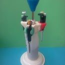
Step 11: Connect and Play the Fluidic Ink "Light Organ"

Proceed as follows:
- connect the 7 LEDs of the LED bar to a fluidic connector having 9 connected holes.
- Connect one hole of the connector to the vacuum pump Connect the last hole of the connector to the fluidic pushbutton.
- Close the outlet hole of the pushbutton with a fluidic stopper.
- switch on the vacuum pump by pressing the pushbutton the LEDs should switch on alltogether.
For use in the dark fill LEDS with fluorescent inks and switch on your UV-lamp/ blacklight.
The coloring intensity will depend on how hard you push on the button. The button acts as a primitive finger pressure sensor that allows you to "play" the LEDs following the music beat. In a new version I will make the button larger since at present it is not very comfortable to use, as tiny as it is.
Step 12: Build a Vacuum Powered Fluidic Ink LED Chaser - No Electronics !


LED chaser circuits
If we were to build an electronic LED chaser or running light circuit we could use for instance an Arduino or more simply some kind of digital logic integrated circuit such as a IC555 to build an oscillator and a IC4017 CMOS decade counter/ Divider to produce the LED blinking sequence (theorycircuit's instructable) or even more simply use a few transistors, capacitors and resistors, building a so-called "ring-oscillator" (see for example Insonicbloom's instructable).
For my fluidic "LED light chaser" circuit I have choosen to use a fluidic ring-oscillator circuit. In analogy to the electronic counterpart it uses fluidic transistors (valves) and resistors (small channels) and fluidic capacitors (chamber and tube volumes).
Ring oscillators
The working of a ring-oscillator is based on logic inverters. In a ring oscillator the output of one inverter is connected to the input of the next inverter and so on and finally the last inverter's output (there must be an uneven number of inverters) is looped back to the input of the first inverter. The output of the last inverter will allways be in a state opposite to the input of the first inverter. This instable situation produces oscillation. The frequency of the oscillator will depend on the time delay produced by each inverter.
In the fluidic inverter when a vacuum (HIGH) is applied to the gate (membrane) of the valve the membrane lifts and opens a passage between the two valve terminals so that air can flow from the hole open to the atmosphere through the resistor channel to the vacuum pump. Because of the pressure drop on the narrow/long resistor channel there will be no significant vacuum level at the output hole (LOW). That is a vacuum signal at the input will be transformed to a "atmospheric pressure" signal at the output , and viceversa.
The outputs of inverters in a ring oscillator are each opposite to the preceeding one. So if you connect a row of LEDs to the row of outputs of a ring oscillator you will get a somewhat confusing blinking sequence. A more interesting outcome would be to have a "running light effect" where you have the LEDs "on-state" moving from left to right in the row of LEDs or the other way round. To get this effect you need to connect the row of 5 LEDs in a specific way to the series of 5 inverters. If the first LED (we call it P1) is connected to the output of inverter 1 then the second LED (P2) must be connected to the output of inverter 3, the third LED (P3) to output of the fifth inverter, the fourth LED (P4) to the output of the second inverter and the the fifth LED (P5) to the output of inverter 4.
Step 13: Make a Fluid Logic Integrated Circuit


No joke ! Here you find the instructions to make an IC !
The nice thing with fluidics is that you can easily design and build your own integrated circuits !! For instance in my pulsing fluidic heart micropump instructable the small gadget is a fluidic IC which contains a 3 stage ring-oscillator + 2 fluidic diodes + 2 fluidic LEDs (heart shaped).
In the present instructable I have used a fluidic IC containing five identical inverter circuits mimicking the well known digital logic SN7404 hex inverter IC. Each inverter consists of a valve (transistor) and a resistor.
Curiously the size of my IC is not much bigger than the size of the chip fabricated by Texas instruments :-)
Prepare materials
I recovered a thin (0.6mm) polycarbonate sheet from an unused DVD by splitting it in half using the X-acto knife. To remove the metal layer after splitting the DVD use scotch tape.
I then cast a 0.3-0.4 mm thin silicone membrane as done for the LEDs on a glass plate smeared with dishwashing soap. Once solidified handle with care. If the membrane gets dirty clean it tapping on it with the adhesive side of scotch tape or plumbers putty.
Milling
First mill the "fluid layer" in the 3.85 mm thick plexiglass plate.The milling of the fluid layer requires front and backside milling, so start out to mill alignment holes in the plexiglass plate that fit the positions of alignment holes in your fixture. Produce two of these "fluid layers". You will use one as a "Punch mask" later.
I milled the conical tube connection holes using a 1 mm diam ball mill.Then I turn the plexiglass plate upside-down using the alignment pins on the plexiglass plate and my milling fixture. Then I mill the fluid channels using a sharp scoring/engraving mill bit. Finally I cut out the chip using a 2 mm diam flat end mill.
To mill the 0.6 mm thin polycarbonate sheet I stick it on my CNC milling fixture with double-sided adhesive tape. I use a sharp scoring/engraving mill bit to engrave the channels and membrane expansion chambers and cut out the chip with the same tool.
Assembly
To assemble the IC you first need to punch holes in the thin silicone membrane at the positions corresponding to the "input" holes of the plexiglass plate ("fluid layer"). To punch the holes use a flattened 18 gauge needle tip and two IC "fluid layer" chips as a punch mask similarly to what I have described in step 5. Sandwich the silicone membrane (already cut to size) between two plexiglass "fluid layers" and use the flattened gauge needle as a punch and the "input" hole in the "fluid layers" as a guide. You need to punch only 5 holes in the positions of the "input" holes.
Once the sized and punched membrane is ready clean it by tapping carefully on it with the sticky side of scotch tape or with plumbers putty. Then position it on the "fluid layer" with the holes corresponding to the "input holes". Finally cover with the "control layer".
Note: there is no need to screw the layers together since the only fluid that will circulate in the chip is air and the vacuum which serves as "power supply" for the IC as well as the stickiness of the silicone membrane are sufficient to keep the IC assembled.
Testing
- connect the vacuum pump to one of the POWER holes in the IC
- connect a fluidic LED to the OUTPUT
- Once you switch on the vacuum pump the LED should be ON since there is no vacuum applied yet to the INPUT, which means the INPUT is LOW and therefore the OUTPUT is HIGH, which means there should be vacuum at the output. If not try tapping on the chip to verify that there are no leaks and check the correctness of the IC layout and assembly.
- connect a syringe to the INPUT and pull on the syringe to produce suction, thereby applying vacuum (HIGH) to the INPUT. You should see the LED switching OFF since the HIGH at the input is transformed to a LOW at the output, which means there should now be atmospheric pressure at the output.


Step 14: Make a Fluidic Printed Circuit Board and IC Socket


Make the oscillator PCB
The oscillator PCB requires front and backside milling, so start out to mill alignment holes in the plexiglass plate that fit the positions of alignment holes in your fixture.
I milled the traces on the PCB using a 1 mm diam flat end mill. Then I turn the plate upside-down and re-align it on the fixture using the pins. Then I milled the conical tube connection holes using a 1 mm diam ball mill. Finally I cut out the board with a 2 mm diam flat end mill. As for the PCB of LED bar you finish the board by sealing the channel side with a sufficiently wide scotch tape or paint protection film as already described.
Make an IC socket
For mounting the IC on the PCB it is convenient to use a kind of IC socket. The socket in this case is made in the form of a plastic bar with holes of diam equal to the outer diamater of the Tygon microbore tubings, that is 0.060''. You will need two of them - one for each row of pins of the IC.
The sockets are also used to prepare the IC pins by cutting Tygon microbore tubing to a uniform length. To this purpose insert two tubings into the outer holes of a socket and then slide a second socket over the first. Then fix the socket on the PCB using the holes for the IC in the PCB. You can then use a sharp knife to cut the tubes that protrude from the socket stack at the surface of the socket. By inserting other tubes into the sockets while still on the PCB you will be able to prepare a number of short tube segments of equal length that will serve as the pins of the IC. Once prepared a sufficient number of pins, remove one of the sockets and mount it on the free IC holes on the PCB. The sockets finally serve to keep the IC pins "upright" so that you can easily "plug-in" the IC.


Step 15: Assemble, Connect and Play With the Fluidic Ink LED Chaser


Proceed as follows:
- To mount the IC correctly refer to the board layout picture above. Note: leave the "ground" holes of the IC open to atmosphere. Don't insert any tygon tubings in these holes. There are two ways to mount the IC. Either you insert the short tygon tubing pins in the oscillator board using one "IC socket" for each row of pins, or you insert them on the IC first, using a "IC socket" for each row of pins on the IC. Once inserted both rows of pins press the IC on the oscillator board with its socket.
- Cut a number of tygon tube segments to connect the oscillator board to the LED bar(s). The length will determine the oscillation frequency. The longer the tubes are the lower will be the frequency but the variations are not big. In any case the circuit will oscillate at a frequency of around 1 Hz.
- Connect at least one LED bar (or alternatively 5 individual fluidic LEDs) to the oscillator board using the tygon tubes. For correct connections see the "component mounting" indications in the picture above.
- close unused holes in the PCB with fluidic stoppers or scotch tape
- connect the hole indicated with "Power" to the vacuum pump and switch on the pump.
For use in the dark with fluorescent inks, switch on your UV-lamp/ blacklight.
You should see the LEDs blinking in sequence, producing a "running light" effect or if you have just one LED connected you should see it blinking.
Troubleshooting:
- check that the IC is well seated in its socket
- check the vacuum. It should be at least 0.4 bar below atmospheric pressure (absolute pressure 0.6 bar)
- optimize coloring of the LEDs by acting on the screws
- change the length of the tubings, both those between the oscillator board and the LEDs and the one between your vacuum pump and the oscillator board. The latter should be as short as possible to get maximum vacuum (power) delivered to the circuit
.
Have fun !
Especially awesome with fluorescent inks !
Invent !
Lots of ideas come to my mind, like upgrading the circuit to allow the frequency to be changed/increased. To produce a LED chaser with a variable frequency I think the simplest fluidic circuit should be use a fluidic "shift register". Also to reduce tubing and PCB trace fluidic capacitances which slow down the oscillator, I am thinking to decouple the LEDs and the inverters by using some "amplifying fluidic valves" that I still need to develop. So there is a lot to be invented or at least "reinvented".
I hope I have stimulated you to start inventing and creating your own fluidic components and circuits !
So I'm curious with what "fluidic" ideas you come up !

Runner Up in the
Full Spectrum Laser Contest 2016

Participated in the
Make it Move Contest 2016


