

Introduction: Alexa Controlled Smart Lights+More

The idea
The idea for this project was to create a loT device that was similar to the well known Philips Hue lights or the WeMo Light Switches because they are extremely expensive. However, this exact technique can be applied to pretty much anything with a remote, like your garage or remote sockets.
What you will achieve
By the end of this project, you will be able to control your lights from a website and also an Amazon Echo Dot.
The reason I think this is a cool project compared to other similar ones I have seen online as this one requires no wires running to the light switch is very cheap as you don't need lots of special bulbs. Making it very clean and practical.
If you have any suggestions feel free to comment or contact me!
Also, this is my first project so if you enjoyed it, please give me a vote :D
Follow as I intend to do more home automation projects in the future.
Step 1: What You Will Need


Parts:
- Raspberry Pi + SD card to fit (Any should do but I used an RPI B) | £4 - £30
- Optocoupler 4-DIP (1 per button you wish to control, I used theses ones Opto-Coupler) | £0.79 Each
- Remote controlled light switch (I used this one Light Switch) | £13.85 (You can get other models)
- Resistor 330Ω (1 resistor per optocoupler) | Very cheap, 5p per one
- Wire / Jumper cables (Any wire / I used Jumper cables) | £1.61
- * PCB (optional, I used PCB but ANY will do) | £2.40
Total - £18.70 (Already had the RPI)
Tools:
- Soldering iron
- * Hot glue (Not needed but quite useful)
- * Multimeter (Used to find + and - ends but an alternative method can be used if you don't have one)
- * Breadboard (I used mine to get everything working before I soldered to the PCB)
Step 2: Rewiring the Light Switch


Note: Theses are live, be very careful if you don't feel comfortable ask an electrician.
1) Go and turn the fuses off for the lights you are changing at the fuse box.
2) Go to the light switch and confirm that the power is off by flicking a switch a couple of times.
3) Then carefully unscrew the plate of the light switch and pull it away from the wall, but some switches can be different.
You can check if the cables are still live by checking it with a screwdriver like this (Screwdriver) or a multimeter if yours supports it.
4) Now I recommend that you take a photo of the wires before you do anything.
5) My switch was metal so needed a ground cable linked to the metal, this is usually the yellow and green wire. But you may not have one so don't worry if you don't you will not need it. But if you do have one just unscrew it and pull the wire free and tuck it away.
6) I then unscrew the COM cables they should be labelled and pulled the link cable out if there is one, yours may only have one, don't worry that's okay.
7) Next, I unscrewed the L1 and L2 mine were not labelled this but you can tell as they are the only other cables.
8) I then place the L1 cable into the new switch and the L2 in the L3 (This is because in the instructions of switch it said for 2 gang lights use L1, L3 make sure to read yours.) Then screw them up tightly.
9) On the new switch, there was only one COM cable socket so I put COM1 and COM2 in the same socket which was labelled L, therefore I would not need the link cable anymore.
For more detail check here downlights.co.uk
Step 3: Setting Up the Raspberry Pi

The first thing to do was have a fresh install of Jessie light, I am using lite for this project as there is no need for the graphical interface as we will only be using commands, feel free to use the full version if you are not comfortable.
- Download the latest ISO - https://www.raspberrypi.org/downloads/raspbian/
- Then you need to flash this onto your SD card, I used Win32DiskImager but if you are on a different OS or are struggling go to https://www.raspberrypi.org/documentation/installa...
- Then plug the SD into the Pi and power on and log in | the default login is "pi" and password is "raspberry"
- Connect the Pi to your internet, I used an ethernet cable to do this but if you have a wifi dongle you need to run this, (Or follow this tutorial LINK)
sudo nano /etc/wpa_supplicant/wpa_supplicant.conf
You will be presented with the file you need to add the lines, (Replace the things inside to quotes with your details)
network={<br>    ssid="The_ESSID_from_earlier/Network Name"
    psk="Your_wifi_password"
}
Now save the file by pressing Ctrl+X then Y, then finally press Enter.
Then reboot,
sudo reboot
Step 4: Enable SSH and Change the Password

This step is optional as you don't need SSH on but makes the rest of steps easier.
1) Run the command
sudo raspi-config
A blue screen should appear, use the arrows keys to scroll to advanced options (7) and click enter go to ssh (A4) and press enter, and then move to yes on the pop-up.
2) Reboot the Pi
sudo reboot
3) Change the password
Log back into the Pi, then run,passwd
Then enter your old password (default for RPI is “raspberry”) and then your new password.
4) Get the IP address of the Pi
ifconfig
Find your network adapter and the address should look like 192.XXX.XXX.XXX Near the top of the blocks of text.
5) Connect over SSH
Use the IP address we found with the command "ifconfig" and put it in your favourite ssh program.
I am using puttyfor PC but for MAC you can just use the terminal as it is built in (please google of you need help with this) and Linux users I assume you already know.
Step 5: Install WiringPi

WiringPi Install - We need to install this as it allows us to easily control the GPIO pins of the Raspberry Pi
1) Update your Pi
sudo apt-get update<br>sudo apt-get upgrade
2) Get GIT
sudo apt-get install git-core
3) Get the wiring PI software
cd
git clone git://git.drogon.net/wiringPi
4) Go to the directory
cd wiringPi
5) Then run
./build
Testing - Then test the software by running
gpio -g mode 22 out
gpio -g write 22 1
This will set the GPIO pin to 22 to the correct mode and also turn the pin on, to see if this worked run this to read the pin if it is ”1”
gpio -g read 22
Set the pin back to "0" / OFF with
gpio -g write 22 0
Step 6: Installing the Web Server

1) We need to install apache and PHP to make the webserver,
sudo apt-get install apache2 php5 libapache2-mod-php5
2) After the install again find the local IP of your Pi by typing (should look like 198.XXX.XXX.XXX)
ifconfig
3) Next, type this into your browser on another computer and you should see the apache page saying “It works!”
Step 7: Creating the Website
We need to replace the apache website with one to control the GPIO pins.
1) Go to the directory where the site files are,
cd /var/www/html
2) You can then type “ls” and you will see the index file, but we need to delete this and make a new one,
sudo rm index.html<br>
sudo nano index.php
3) Inside this file, we need the code to control the GPIO pins with PHP
Note - You can run the PHP function to turn the pins on by changing the mode and then writing "1" for on and a "0" for off.
system ( "gpio -g mode 22 out" );
system ( "gpio -g write 22 1");
You can just use the file I have to make to do this just copy and paste in the open nano or you can create your own website file as mine is very basic.
Just download the text file I have provided and copy everything from the file and paste into the nano.
Attachments

Step 8: Information - Optocoupler


The idea was to control the button via the GPIO pins and to do this I decided to use an optocoupler also known as opto-isolator.
To use these, we know what they are and how they work so we can impendent them.
What is an OptoIsolator?
Excerpt: An optoisolator (also known as an optical coupler, optocoupler and opto-isolator) is a semiconductor device that uses a short optical transmission path to transfer an electrical signal between circuits or elements of a circuit while keeping them electrically isolated from each other. These components are used in a wide variety of communications, control and monitoring systems that use light to prevent electrical high voltage from affecting a lower power system receiving a signal.
How to use it?
We will need to unsolder the button from the board of the
remote then will need to connect 2 pins on one side of the opto-isolator in the place where the button was and the other two pins connect to the ground and 1 GPIO pin of the raspberry pi.
Step 9: Building the Electronics


Note: I numbered the pictures according to the step
1) We need to take apart the remote to get a look at what the circuit board was like, I just unscrewed the screws on the back and removed the plastic.
2) Next, we needed to remove a button from the board, I did this by using a soldering iron and heating up both ends and then pulling it away from the board (I used quite a bit of force here)
3) I could here just solder the optoisolator right onto the board but before you did this you need to check which pin is which, but I wanted to test it all works with a breadboard first. So, I solder on 2 wires on the bare wire that’s left and the other end can be pressed into my bread board.
4) I needed to know with one of the button pins was positive(+) and which was negative(-) I used a multimeter by connecting the COM / negative(-) / black cable to the ground on the remote and pressing the other the each pin of a button the one that has a reading, the one with a reading is + end.
Alternatively, we know that the '+' side will have power if the
device is powered, when the button is pressed it closes the connection with the '-' side which completes the circuit meaning that if you follow the tracer lines from a button to the processor of the board (black chip or black blob) you know that this one must be negative(-) meaning the other one must be + as it has to be connected to the power of the battery.
Step 10: Wiring the Optocoupler


Now we have replaced a button with two wires and know which is the positive(+) and negative(-) we can wire it to a bread board for testing. One thing you need to be very careful with is which pin is which so go and get the semantics for you optoisolator as the pins can often change but most likely they are the same as the ones I provided.
Tip - You know which way is up by being able to read the text on the optocoupler.
Anode – Connects to a GPIO pin through a 330Ω resistor we use 330 Ω as the optoisolator is very similar to a LED.
Cathode – Connects to the Ground(GND) of the Raspberry PI.
Collector – Connects to the positive(+) end where we took out the button.
Emitter – Connects to the negative(-) end where we took out the button.
After the wiring is complete you can to the website that we created before and test if it’s working. It was quite clearly able to see mine was working correctly as the blue LED came on.
Step 11: Creating a Custom PCB (optional)


I soldered the components from the breadboard to a blank PCB and then hot glued everything down for security. (Yes, I know I went overboard on the hot glue XD)
I then thought that the only problem with this now is how the remote is still powered by a battery and how it would be a pain when it was to run out!
So I had a look at the battery from the remote and it said it was 12V but when testing it with my multimeter and it came out to be about 10V but the problem was the RPI only has a max of 5V on one of the pins.
However, I guessed that 5V would still be enough to power the remote and after connecting the 5V pin to the positive(+) and the ground to the negative(-).
I then tested this and it worked fine!!! :D
Step 12: Connecting Your Pi to Be Controlled Over Internet

At the moment we can on and off our lights within the local network but we can do better than that.
To so this we use service called dataplicity that allows us to access the pi from anywhere from a browser as it will give use a remote shell.
1) Go to dataplicity.com put in your email address
2) Then copy and paste the line into the command line of the Pi (paste in the console is right click) ), then wait for it to finish installing step 3 usually takes a while.
3) While waiting, go to your email inbox and verify, and make an account.
4) After it has installed navigate to the devices page (dataplicity.com/devices/) and click on your Pi
This service gives you a remote shell to your RPI like ssh but over the internet, this is cool but not what we want.
5) Above the console, on the web page, you should see a button saying “Activate Wormhole”, click on this. Then go the new link it gives you in the box. This should look very familiar as this is the site we made earlier, this is good as we now can say go to this site on our phone and control the lights from anywhere in the world as the local website is now live.
Note: If you are having any trouble connecting to the Pi (you say the command and the button is not pushed) then restart your Pi and wait 60 for it to reconnect
Step 13: Connecting the Lights to Alexa


1) To make this work with Alexa we need to go to the website we just made and click on the button that you want Alexa to press and copy the whole link in the address bar, for example (https://XXXXXXXXXX.dataplicity.io/index.php?btn1=true) -- REMEMBER THIS
2) Next, go to ifttt.com Sign in or make an account if you don’t have one.
3) Then start making a new Applet (Click your username and then you will see create new in the dropdown).
4) We will connect “This” with Alexa channel, you just will need to sign into your amazon account.
Then select “Say a specific phrase” and put in the phrase you want but remember you will have to say “Alexa trigger” + Your phrase, I choose the phrase “lights” so I will have to say “Alexa trigger lights” to toggle my lights.
6) We then will connect “That” with the Maker channel and select Make a web request.
Then fill in the URL with the one we remembered earlier, change method to “GET”, Content Type to “application/json” and leave Body blank.
Note: If you have two or more buttons you want to connect to Alexa just repeat this step and change the link to the one for the other buttons.
Note: If you are having any trouble connecting to the Pi (you say the command and the button is not pushed) then restart your Pi and wait 60 for it to reconnect
Step 14: Final Touches


Now you should have a fully working smart light switch that you can control from anywhere in the world.
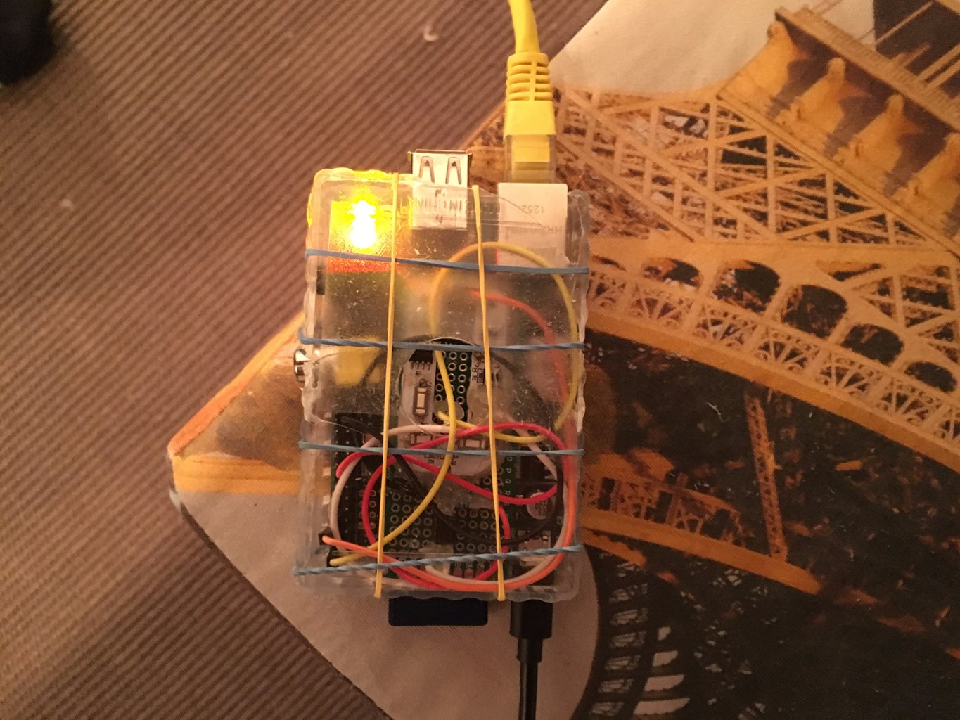
Lastly, I just made a small container from an old deck of card to fit my Raspberry Pi and custom PCB, so it could neatly be plugged in by this is not necessary.
I then tested to show you it all working.
Feel free to add any suggestions to the project, I may be adding more things to make it even smarter like motions sensors and better GUI so keep checking back!!

Participated in the
IoT Builders Contest

Participated in the
Remix Contest 2016


