

Introduction: An Affordable Vision Solution With Robot Arm Based on Arduino


When we talk about machine vision, it always feels so unreachable for us. While we made an open-sourced vision demo which would be super easy to make for everyone. In this video, with the OpenMV camera, no matter where the red cube is, the robot arm could pick it up and place it in the fixed position. Now let us show you how to make it step by step.
Step 1: Preparation.

Hardware:
1. uArm Swift Pro * 1
2. Arduino Mega 2560 Shield * 1
3. Arduino Mega 2560 * 1
4. Object for vision(Red) * 1
5. Cables(USB Cable, 4P 1.27 Cable, DC Power Cord) * Several
6. uArm Base Extension board * 1
7. Suction Cup * 1
8. OpenMV Extension Board * 1
9. OpenMV board with Fixing Base * 1
10. Connection for OpenMV and uArm * 1
11. Case for the OpenMV * 1
12. M3 Screws * Several
Software:
1. Arduino IDE (www.arduino.cc)
2. OpenMV IDE (www.openmv.io)
3.Vision.ino for Arduino MEGA2560 [Github]
4.Color_tracking_test.py for OpenMV [Github]
5.UArmSwiftPro_2ndUART.hex for uArm[Github]
Github: https://github.com/TonyLeheng/Vision-Pick-and-Place
Step 2: Connect the Arduino to PC.

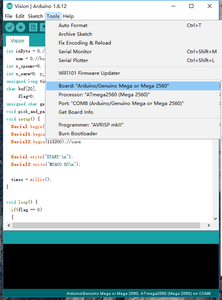
Step 3: Open Vision.ino (https://github.com/TonyLeheng/Vision-Pick-and-Place), and Set the Option Correctly.
Step 4: Click the "Upload" Button.

Step 5: Connect the UARM to PC.

Note: uArm Swift Pro is designed based on the Arduino Mega2560, normally it communicate with PC with uart0 by USB port, while in this scenario it needs to use the uart2 in the 30P extension port so we have to change the firmware, for more detail please check developer guide.
Step 6: Open the XLoader (xloader.russemotto.com/) and Load the UArmSwiftPro_2ndUART.hex (https://github.com/TonyLeheng/Vision-Pick-and-Place)

Step 7: Click the Upload Button.

Step 8: Connect the OpenMV to PC.

Step 9: Open the Color_tracking_test.py (https://github.com/TonyLeheng/Vision-Pick-and-Place) by OpenMV IDE and Click the Connect Button to Detect the Device.

Step 10: Then Click the Start Button.

Step 11: Rotate the Lens to Make Sure the Image Is Clearly Enough.

Step 12: Save the File to the OpenMV.

Note: If the code downloaded successfully, re-plug in the USB cable you
could find the blue LED would be on for several seconds.
Step 13: OpenMV Module Installation.


OpenMV (NO.1) is just a PCB board, so we offer both the PCB shield (NO.4) and mechanical parts (no.2,3) to make it much easier to use with uArm.
Part (NO.2) should be fixed in the suction cup.
Part (NO.3) is the cover of OpenMV module.
With the mechanical parts, we could fix the OpenMV module to the end-effector of uArm easily.
Step 14: Arduino Module Installation.


Arduino Mega 2560 (NO.1) is the center CPU of the entire system, shield (NO.2) is the extension board which makes the connection much easier. Part (NO.3) is a connector board with Velcro which helps to extend the wire when it’s too short. Put all these things together.
Step 15: Connect All the Modules Following the Pictures.


The 4P 1.27mm wires are used to connect the uart port from both uArm and OpenMV to the Arduino Mega 2560.
The 2P power cord from the shield makes the powering easier, three devices just need the original robot adapter (12V5A).
Step 16: The Connector Board With Velcro Extend the Length of Wires. the Connection Would Be More Stable Since It Can Be Fixed in the Lower Arm Tightly.

Step 17: Fix the Suction Cup to the End-effector.

Step 18: Power the Entire System (The Original UARM Power Adapter).

Caution: After powering the entire system, the OpenMV and MEGA2560 would work immediately, while uarm has its own power switch, and we should power it on manually.
Step 19: System Frame.

-------------------------------------------------------------------------------------------------------
Created by UFACTORY Team
Contact us: info@ufactory.cc
Follow us on Facebook: Ufactory2013
Official web: www.ufactory.cc


