

Introduction: An Arduino-powered Microplate Spectrophotometer


Spectrophotometers are common pieces of equipment in a bioscience lab. They perform one simple function - to measure how much light a liquid absorbs at a particular wavelength. Many chemicals absorb light at a set wavelength, and so this can be used to measure the concentration of the chemical in the solution. Even when the substance to be tested doesn't have a useful absorbance, its presence can be coupled to an assay that produces a coloured product (like with a home pregnancy kit). Because of the flexibility of this technique, spectrophotometers can be used to measure the presence of an almost limitless numbers of things.
This Instructable details the final-year lab project of two undergraduate biochemistry students in my lab - Peter Elphick and Ed Tye. We wanted to make a spectrophotometer that would measure the concentration of a dye called OPD; a common dye in biological assay kits. In addition to reading the absorbance of the samples, we wanted to make a spectrophotometer that worked with 96-well microplates. These are disposable, multi-sample plastic dishes and are the backbone of assays in academic and pharma bioscience labs. They hold 96 samples of up to 0.35mL, arranged in a grid. Pharma labs like them because they lend themselves to robotic handling and high-throughput assays.
We reckon that the final machine cost about £500 ($750), although a lot of that could be saved if you machine your own frame.
Lastly, we'd like to thank Adrian Crimp and everyone in the University Physics Workshop, and Derek Carr in the Electronics Workshop for all of their help and advice.
Step 1: Notes Before Starting...
- We chose to build using the Arduino Mega because we needed a lot of output pins to control the two stepper motors. You could use H-bridges to get around this and then you could use a UNO instead.
- We chose cheap, low-powered stepper motors in the (mistaken) belief that we could power these directly from the Arduino board. In hindsight it would have been a lot simpler to start with more powerful steppers.
- Along those lines, we probably could have avoided the power regulation circuit by a bit of forward thinking to make sure we got everything running at the same voltage.
- We used Makeblock to construct the x-y table. This was fantastically useful, as we had no idea how to build this and it took a lot of tinkering to get it right. Makeblock is perfect for this kind of prototyping. Having made it, it could certainly be taken apart and remade using simpler combinations of Makeblock components, or even machined from aluminium bar and sheet. This would be a lot cheaper.
Step 2: Parts List
x-y table:
M4 screw thread
1.2mm aluminium sheet
3mm aluminium sheet
Electronics:
Arduino Mega 2560
2 x 28BYJ-48 Stepper Motor
2 x ULN2003 driver board
hook-up wire (e.g. 20 AWG)
LED: 470nm (blue) 3mm with 50° viewing angle
LM7809CT (9V) voltage regulator
heat sink for voltage regulator
2 x 100 nF capacitors
7 x 220Ω resistor
4.7kΩ resistor
DC power supply: 12V, 2.5A with a 2.1mm barrel plug (centre pin positive)
panel-mounted momentary switch
panel-mounted 2.1mm power socket
panel-mounted on/off rocker switch
From the Arduino starter kit:
alphanumeric LCD (16x2 characters)
photoresistor VT90N2 LDR
4 x momentary switch
10kΩ rotary shaft potentiometer
Case:
Interscale M Standard Case 133x399x310mm

Step 3: LED/ Detector Circuit and Code
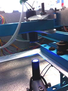
This is the simplest part of the project. The LED is lit by the Arduino to make a reading. The light is detected by a simple photoresistor. We put the LED and the photoresistor into simple holders made from marker pen caps. We filled these with blu tack to hold the components in place and put plastic sleeves over the leads to prevent them shorting. We thought we might need a small lens to focus the light, but the pen cap did a great job. We started with a cheap blue LED, but then swapped it for a 470nm LED. This was matched to the wavelength that we wanted and had a pretty narrow emission spectrum (shown in the datasheet). If you want to measure another compound, you just need to swap to a LED with the appropriate wavelength.
Code:
LDRValue = analogRead(LDR);
LDRValue2 = LDRValue - 4;
Transmittance = (LDRValue2 / LDRValueMax) *100 ;
Absorbance = (2 - (log10(Transmittance))) * 7;
total= total + Absorbance;
readIndex = readIndex + 1;
delay(200);
if (readIndex ==5){
average = total / 5;
The reading from the photoresistor is stored as the value LDRValue.
The baseline reading (4 in this case) is subtracted. The baseline reading is the reading when the LED is turned off and represents the background light hitting the detector. You will need to find this value for your machine. The easiest way to do this is to cover the LED and take a reading. We were surprised how low the value was.
The Arduino then calculates the transmittance value - the reading expressed as a % of the maximum light. To do this it compares the reading to the fixed integer LDRValuemax, which for us was 650. Again, you will need to calculate the value for your machine, which you can do by taking a reading with just air between the LED and the detector.
The Arduino then converts the transmittance value to a true absorbance value. It also multiplies by a scale factor of 7. We have no idea why we needed this scale factor.
For accuracy, the machine takes 5 readings from each sample, adding them together in the 'total' and then dividing by 5 to obtain the average.
Step 4: Making the X-y Table


This took a long time to get right, much of that time taken by trying to simplify the mechanics and reduce the overall size. Using Makeblock really helped with this, as we could take it to pieces as reassemble it as much as we wanted. It has really good strength and accuracy too. We ordered the robot kit and also two thread drive kits. The robot kit was a great mix of different components, but we used very little of it in the end. The thread drive kit was very useful as it had the M4 thread and the articulated couplings we needed.
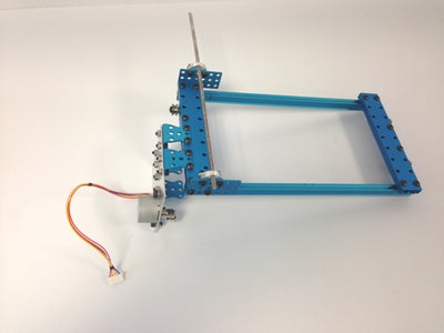
We decided that we should keep the LED and the detector fixed, as they needed to stay in alignment. You can see these fixed to the base frame in Picture 1. This choice meant that we needed to move the microplate. The basic structure of the x-y table is the base frame, with two moveable frames placed on it, set at right-angles to each other. We needed the frames to move with almost no friction, and we found that the Makeblock V-slot bearings matched with the Slider256 rails were a really good combination for this (Picture 2).
Pictures 3 and 4 show the first table with its stepper attached through a piece of cut and drilled 3mm aluminium sheet. There are 2 V-slot bearings on each side of the frame which sit on the slider rails on the base frame.
The second table (Picture 5) has a cut-out piece of 1.2mm aluminium sheet which serves to hold the microplate. It has 4 V-slot bearing to let it hang from the rails in the first table. Picture 6 shows the second table mouted on the first table and ready to sit on the base frame.
Picture 7 shows the final x-y table (with the two steppers and the threads removed)
Step 5: Adding the Stepper Motors
We chose 28BYJ-48 stepper motors to drive the x-y table. These are very cheap and widely used. They have a high gearing ratio, which gives them plenty of torque to move the table - but makes them very slow. We got a bag of them from Amazon that included the ULN2003 driver boards you need to run them. We cut 3mm aluminium sheet to make a simple bracket to mount the steppers to the frame. To start with, we connected the shaft of the stepper directly to the M4 screw thread with a rigid connector. This was a problem, as it magnified small alignment errors and caused the table to kick. The Makeblock thread drive kits came with a Universal Joint, which allowed flexible coupling. We drilled out one side to the diameter of the motor shaft and used these to couple to the thread.
Step 6: Running the Steppers
The 28YBJ-48 stepper is a 4-coil stepper with a high gearing ratio (quoted as 64:1). There are some helpful tutorials here:
http://42bots.com/tutorials/28byj-48-stepper-motor...
https://arduino-info.wikispaces.com/SmallSteppers
And a great, general stepper Instructable here:
https://www.instructables.com/id/Intro-to-Stepper-Motors/
They connect to the Arduino through a ULN2003 driver board (the stepper cable plugs in one way only, so don't worry about getting the wiring wrong). You can run these motors with the built-in Stepper library in Arduino. This activates each coil in sequence, moving the rotor through 4 positions to make one rotation. This is really simple, but limits the speed of the stepper. If the coils switch too quickly, the rotor can't keep up and the motor freezes (you will hear a humming noise with some vibration). We used the AccelStepper library , which allows for more sophisticated control of the motor. It allows you to use an 8-step sequence to move the rotor in half-steps, making it easier for it to keep up, and hence reach faster speeds. It also allows you to use acceleration, which also increases the maximum speed. Trying to get the rotor to move immediately to the final speed from rest will make the rotor stall. Accelerating up to the final speed allows the momentum of the rotor to build up, letting you get to faster final speeds. The AccelStepper library takes a bit of getting used to, but it allowed us to run the motors significantly faster. You will need to download the library from the link given and install it.
Set up
include <AccelStepper.h>

// Motor pin definitions

#define motorPin1  38     // IN1 on the ULN2003 driver
#define motorPin2  40     // IN2 on the ULN2003 driver
#define motorPin3  42     // IN3 on the ULN2003 driver
#define motorPin4  44     // IN4 on the ULN2003 driver
define motorPin5  39     // IN1 on the ULN2003 driver
#define motorPin6  41     // IN2 on the ULN2003 driver
#define motorPin7  43     // IN3 on the ULN2003 driver
#define motorPin8  45     // IN4 on the ULN2003 driver

// Define Parameters for Steppers

#define HALFSTEP 8
#define STEPS_PER_MOTOR_REVOLUTION 32
#define STEPS_PER_OUTPUT_REVOLUTION 32*64 // =2048
AccelStepper stepperX(HALFSTEP, motorPin1, motorPin3, motorPin2, motorPin4);
AccelStepper stepperY(HALFSTEP, motorPin5, motorPin7, motorPin6, motorPin8);
Stepper stepper_X(STEPS_PER_MOTOR_REVOLUTION, 38, 42, 40, 44);
Stepper stepper_Y(STEPS_PER_MOTOR_REVOLUTION, 39, 43, 41, 45);

int Position1 = 0;
int Position2 = 0;
The output ports on the Arduino that connect with the motor driver boards must be defined. Each stepper motor is connected to a driver board that modulates the output from the Arduino and converts it into the correct sequence of pulses to be sent to the electromagnets of the stepper.
The 8-step mechanism is defined as HALFSTEP as a parameter to control the stepper motors. This provides the information to encode for the rotation of the stepper motors using the 8-step mechanism. The step angle in the 8-step sequence (how much a single step rotates the toothed gear) is 5.625˚ (64 steps per revolution). The gear ratio is 1/64, so are 64x64 (4096) steps per revolution of the output shaft of the motor. The positions of the stepper motors are also defined as 0 at their starting position. Position1 is the position variable of stepper1; Position2 is the position variable of stepper 2. PositionX defines the column on the microplate that the sensor is above (1-12), which is controlled by stepperX; PositionY defines the row on the microplate that the sensor is above (A-H), which is controlled by stepperY. At the starting position both position variables are 0, which equates to the sensor lying above well A1
// Set stepper speed and acceleration

void setup(){
stepper1.setMaxSpeed(3000.0);
stepper1.setAcceleration(500.0);
stepper2.setMaxSpeed(3000.0);
stepper2.setAcceleration(500.0);
}
The setup is enclosed in curly brackets: {…}. The speed and acceleration of the motors is defined for both motors. These variables were chosen to be well within the stepper motors’ capabilities to prevent stalling, but fast enough for the program to be excessive in length. The speed, 3000 (steps per second), equates to 44rpm; the acceleration, 500, equates to 7.3rpm^2
Moving the table
delay (2000); //Take reading of A1
Before moving the motors there is a delay of 2000ms (2 seconds) to allow the first sample (A1) to be analysed
stepper1.runToNewPosition(stepper1.currentPosition() +52406);
Position1 = Position1 +1;
delay(5000); // Stepper1 with delays between each turn
Stepper 1 is rotated 52406 steps, which equates to moving the microplate the 9mm between two adjacent samples. Once the stepper has moved to the adjacent well, the PositionX variable is increased by one unit to define that the column that the sensor lies above on the microplate has increased by one (for example, from well A1 to A2). The stepper pauses to allow the well to be analysed.
if (Position1 == 11){   //after 11 turns of stepper 1 (at A12)
stepper2.runToNewPosition(stepper2.currentPosition() +52406);
Position2 = Position2 +1;
delay(2000);
stepper1.runToNewPosition(0); //return motor 1 to A1
Position1 = 0;
delay(2000);
}
Therefore the microplate will be moved so adjacent well is below the sensor, pause and repeat until the sensor is above column 12 (PositionX = 11). At this point, the if() clause commands that stepperY shifts the microplate down so the sensor is above the next row (from row A to row B etc.), there is a pause and subsequently the microplate is returned back so the sensor lies above the first column.
if (Position2 == 8){ //after 7 turns of motor 2 (row H)
stepper1.runToNewPosition(0); //return motor 1 to H1
Position1 = 0;
delay(2000);
stepper2.runToNewPosition(0); //return to A1
while(1){}
}
}
The second if() clause commands both motors to return to their original positions (with sample A1 below the sensor) once the first if() clause has been repeated 8 times. At this point every well on the microplate has been analysed so this clause merely resets the position of the microplate for the next use. The code while(1){} commands this clause to only be repeated once. This means that once the microplate has been scanned and returned to well A1 the loop stops and the microplate remains stationary.
Step 7: Mounting the LED/detector


We cut holders for the LED and detector out of aluminium rod. These were cut away to make something like a clothes peg that we could bolt to the Makeblock frame. The pictures show the side and top views of the detector. A similar holder with the LED is fixed to the frame directly below (you can see this in the picture in Step 3). The top holder is on a moveable arm that can swing out of the way of the microplate when you need to take it out. A small magnet holds the arm securely in place. The bolts let us wiggle the detector to get in in perfect alignment with the LED.
Step 8: Adding an LCD Display

The display is a standard 16x2 character LCD (from the Arduino starter kit). A potentiometer controls the screen brightness. The display shows the current sample position (A1, A2 A3 etc) and the absorbance reading. The code sets up a text array (WellNumberY) with the letters of the columns and this is used to translate from the numerical values of the positions (wNY). The row position is stored in WellNumberX. The hardest part was mounting the LCD in the case. Why doesn't anyone sell trim for these? We used double-sided foam tape to mount the LCD to the panel and then duct tape (gaffer tape) to secure it and insulate it from shorting against the x-y table.
Step 9: Adding a Thermal Printer
The LCD display shows the current reading, but means you would have to sit by the machine writing the numbers down. We added a simple thermal printer - basically the kind of printer that prints till receipts. We used the A2 micro printer, which is panel mounted and widely available. The manual is in the Parts List section. The printer uses the Arduino SoftwareSerial library. It is worth playing with some of the settings to get the print clear. Ours are shown below, and there is a great tutorial here.
SoftwareSerial Thermal(51, 53);
int heatTime = 80;
int heatInterval =255;
char printDensity = 15;
char printBreakTime = 15;
The printer draws about 1.5A when it is printing (to heat the ink), so this needs to be taken into account when choosing a power adaptor for the spectrophotometer. We ended up with a 12V adaptor that was rated up to 2.5A and that was fine. We found the printer ran best at 9V (they specify 5-9V).
Step 10: Powering the Components

Originally, we planned to run the steppers directly from the Arduino at 5V. Although you can just about do this with one motor, the current drawn could easily damage the chip. And we had two motors to run, so we needed a separate power supply. We had a 12V DC power supply, but running the motors at 12V was too much, and they heated up significantly. We made a simple power board that split the incoming 12V off to the Arduino and took a parallel feed to a LM7809CT voltage regulator, which took the voltage down to 9V for the steppers. Running them at 9V from their own power supply significantly increased the maximum speed. We also took another 9V feed to power the thermal printer.
The 2.5A available from the DC adapter gave us enough power for the machine. One important thing to know about steppers is that they use most power when stationary, when the coils are energised to hold the rotor in place.
N.B. We needed to bolt a heat sink to the voltage regulator, which got very hot.
The big lesson here was - think ahead. We only really needed the voltage regulator because we were learning about the components as we went along. You could simplify things by using a 9V DC adapter and powering everything from that.
Step 11: I'm Lost and I Can't Find My Way Home

The stepper motors don't accumulate error and so the positioning is very accurate. The problem comes if there is a power interruption. The x-y table 'knows' where it is only relative to where it starts, so if the power goes off, it will think 'home' is wherever it woke up. We spent a long time thinking of ways to deal with this. One possibility was to add contact sensors to allow the table to calibrate itself to a fixed position. We could also have added a flash card writer to keep a record of the position safe if there was a power out. In the end we went for a low-tech solution. We made a simple D-pad out of 4 momentary buttons. Every loop, the code looks to see if these have been pressed and then drives the table in the corresponding direction. The D-pad is a simple piece of perf board with the buttons soldered on (picture shows the back). The length of the connecting wires lets it be tucked away in the case when it isn't needed. This worked really well, and allowed us to easily align the first sample with the LED when we were setting up.
N.B. you will notice in the code that we use the built-in Arduino Stepper.h library to run the steppers during manual mode.
Step 12: Wiring Up the Electronics


We mounted the Arduino, stepper motor driver boards and power board onto a piece of perspex to keep everything tidy. The small number of components were mounted onto a piece of perf board and then everything was soldered up. We included a 'run program' switch, which was mounted on the front panel next to the LCD. When the machine is turned on, the loop checks for this to be pressed before starting the readings. This allows time for putting the samples in.
N.B. we bought a momentary 'on' switch that turned out to be a momentary 'off' switch, which was very confusing until we worked it out. If you look at the relevant section of code:
else if (RunSwitch == 0) { //check if run button has been pressed
Run = 1;
you can see that this is set up for a switch that turns 'off' when pressed. If you use a momentary 'on' switch, you need to change to (RunSwitch == 1)
Step 13: Mounting in the Case


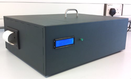
We just about managed to get everything into a Interscale M Standard Case (133x399x310mm). This was a really nice quality case and easy to mount the components in. The frame was secured to the base with M4 bolts and four rubber feet raised it off the table. Once everything was 100% in place, we cut a hole in the top panel and made a simple lid.
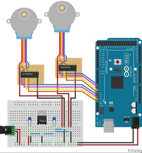
Step 14: Final Code and Circuit Diagrams
The final circuit is shown in the Fritzing diagram above. The Fritzing file (.fzz) and the final Arduino sketch file are below.

Step 15: Running the Machine


To test the machine, we measured a serial dilution of 2,3 diaminophenazine. This the product of a commonly used reaction in a type of bioassay called ELISA. In the assay, the substance to be measured is captured in the microplate well, usually by a specific antibody. An enzyme called horseradish peroxidase is coupled to the antibody and this catalyses the conversion of a colourless compound o-phenylenediamine dihydrochloride (OPD) into a yellow one: 2,3 diaminophenazine. The reaction is shown in the picture above.
The intensity of the colour is directly related to the concentration of the substance being assayed, and the assay can be adapted to different substances by using different antibodies.
We set up a range of concentrations of 2,3 diaminophenazine to test the machine and checked them on a commercial spectrophotometer. The machine we used was a relatively cheap one - about £10,000. The graphs from the commercial machine and our spectrophotometer are shown above.
I have to say, this worked better than we imagined it would. The data are really pretty good, although the commerical machine can read higher absorbances with accuracy - the linearity broke down at about A=1.0 for our machine. At an absorbance of 1, only 10% of the light makes it to the detector and so the sensitivity of the detector becomes important. You will notice that the gradient of the two lines is different, although this could be adjusted by tweaking the calculation in the code. Most importantly, the machine managed to complete a full circuit of the 96 samples in perfect alignment and then return itself to the start point again.
Step 16: Lessons and Future Improvements
- A full run took our machine about 75 min. This is much slower than a commercial machine, which could read a plate in about 30 sec. Better stepper motors would be the simple answer to this.
- We overdid the gearing. We started off worried about the precision of the x-y table, but the combination of the high gearing of the steppers and the pitch of the screw thread meant that we could move in 170nm steps - which is over the top for what is needed here, and slows the process down.
- Our machine struggled a bit with absorbances greater than 1. Above this, the amount of light being measured is tiny, and it is likely that using a phototransistor (more sensitive) instead of a photoresistor as a detector would help with this.
- Most commercial machines can read multiple wavelengths, whereas ours is fixed. It would be relatively easy to have multiple LEDS on a servo that could be switched to give a choice of wavelengths. Commercial machines use a diffraction grating to vary the wavelength of a white light source.
- The printer worked well to record the data, but felt a bit old-fashioned. Swapping the Mega for an Arduino Yun would allow data transfer through a service like Temboo.

Participated in the
Move It


