

Introduction: An Easy Way to Breadboard With the ESP-01 (ESP8266)


The quick Bend-and-Bridge solution helps you prototype the ESP-01 on breadboards.
Key Benefits:
- Easy to build, requiring only a short inline header strip
- Lots of access so you can change jumpers easily during prototyping
- Structurally quite solid so you can remove and reinsert it (albeit carefully)
- An even easier and faster variation is discussed in step 11
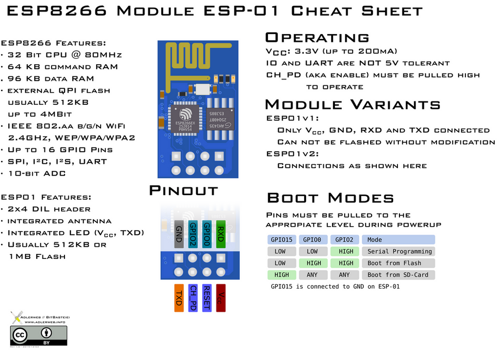
Step 1: Background on the ESP-01
The ESP8266 System-0n-a-Chip made by Espressif is an enabling technology for the Internet of Things. It’s available in a tiny low-cost module known as the ESP-01 which delivers Arduino and WiFi among other capabilities.
Step 2: Problem With Prototyping the ESP-01

An annoying challenge that you may encounter is how to prototype your designs with the ESP-01 since the 2x4 pinout pattern is not a good match for breadboards.
After doing some YouTube and Google searches, I didn’t find a convenient way to connect the module on breadboards. Some approaches were promising, but ended up being “rickety towers”, were fragile, and/or didn’t leave access to connect jumper wires.
The following pictures will help you get the ESP-01 connected to your breadboard quickly, easily, and with a minimum of special parts or skills. I call it the “Bend-and-Bridge” approach for reasons that will, hopefully, soon be apparent!
Step 3: Getting Started

Since you’ll need to handle the ESP-01, it’s a good idea to wear a ground strap. If you don’t have one, at least touch a safe grounded metal item at your workbench before starting. Then hold the ESP-01 module by its edges.
Step 4: Bend Leads Closest to Edge at a Right Angle

There are two rows of pins on the ESP-01, each with four pins. You need to bend the row of pins that is closest to the edge. Use a needle-nose pliers to bend these pins outwards so that they are parallel to the board’s surface. Work-in-progress is shown above.
Step 5: Insert ESP-01 Next to Breadboard Gutter

Align the ESP-01 above your breadboard. The first row of pins (that you just bent) should be vertical above the row of sockets right next to the breadboard gutter. The second row of pins should be horizontal and pointing in the direction of the breadboard trough. Press the module carefully down until the bottom (vertical) row of pins seats into the breadboard.
Step 6: Cut Off Four Terminal Posts From an Inline Header Strip.

Step 7: Bend Short Leads of Inline Header

Again, use a needle-nose pliers to bed the short ends of the header as shown above. Bend each pin a bit more than 45 degrees. You’ll be able to better determine the angle by fitting it as shown in the next picture.
Easier and Faster Approach: You can also skip this step and leave the header unbent. For details, see Step 11 near the end of this article.
Step 8: Align Top Row Pins of ESP-01 and Bent Header

Tilt the ESP-01 and the header towards each other so that their pins align, in effect, forming a bridge. Each pin on the top row of the ESP-01 should be directly below its associated pin on the header. For strength during module insertion and removal, the pins should be as parallel as possible, so you may need to adjust the angles of the header pins as discussed in the previous step.
Step 9: Solder

Now solder each of the four pairs of pins together. This is a bit tricky since you don’t want to heat them more than necessary. A magnifier, good lighting, and a small soldering nib are very handy during this step.
Start by melting a drop of solder on the tip of your soldering iron. Then use that hot drop to heat the first pair of pins by placing the iron on the side of the pins. This process will ensure that both pins heat simultaneously. If more solder is necessary, add solder from the opposite side of the pair of pins and then remove the iron. Repeat for the remaining three pairs of pins.
After you are done soldering all four pairs of pins, you should check resistance across the “bridge” to ensure signal continuity.
Step 10: Profile View

The final module orientation will lean slightly as shown above, however it should be quite sturdy. I’ve made a couple of these and although they can be removed and reinserted (carefully), I’d generally avoid doing so.
Step 11: Easier and Faster Approach

Shown above is a simpler version of the bridge that doesn't require you to bend the inline header pins. It’s easier and faster to build, but not as strong. Additionally, you may have to lean the ESP-01 and inline header more towards each other which makes insertion and removal a bit more difficult.
Step 12: Review the Pinout!

Finally, before wiring up the rest of your circuit, ensure that you have the correct ESP-01 pinout and then keep track of how the pins map onto your breadboard.
I hope that this helps get you going quickly and have fun with your ESP-01 project!


