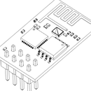
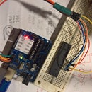
Introduction: Arduino ATtiny Fan or Any DC Motor PWM Speed Controller
I've made fumes extractor from old Dell fan. It's quite powerful: 110mm 12V 0,6A, but unfortunately it's horribly noisy on full speed. I decided to make speed controller for it. I wanted it to be as simple as possible, mounted on fan, thus powered from it's voltage line (12V), potentiometer controlled.
I chose ATtiny45 because main circuit would consist only of ATtiny and potentiometer. Alternative was 555 timer, but I wanted it simpler!
My fan had wire for PWM control, but there's nothing stopping you from using it with any DC motor with additional transistor!
I'll show how to program any ATtinyX5 or ATtinyX4 with Arduino IDE, how I've done my controller, how to use it with any DC motor, and how tu use zener diode as simplest voltage regulator.
Step 1: Prepare Arduino IDE
In Arduino IDE (version 1.6.4 or newer is needed) open preferences window (File>Preferences) and add
http://www.leonardomiliani.com/repository/package_leonardomiliani.com_index.json
into Additional Boards Manager URLs.
Than open Boards Manager from Tools menu, search for attiny and install ATtiny extra Boards.
Now you can select your ATtiny from Tools>Board and Tools>Micro menus.
I used ATtiny45 @ 1MHz - It's internal oscillator, so no crystal is needed. You can also choose 8MHz, but It's not necessary to speed it up so much.
For Attiny85 I recommend 1MHz internal oscillator, BOD disabled option. You can also use ATtiny25 @ 1MHz for this simple motor or fan controller.
Step 2: Prepare ATtiny
You need to set ATtiny's fuses in order to use it as Arduino. This means programming some internal memory, so tiny could know what clock source to use and some other important stuff. It is done by "Burn bootloader" in Arduino IDE Tools menu. Unfortunately ATtinys do not have hardware serial interface so they do not have real bootloader. You need AVR programmer (AVR is family of Atmel microcontrollers containing ATtinys and ATmegas used by Arduino) to program them every time.
Any Arduino board is suitable to be used as AVR ISP (in system programmer).
for UNO and other ATmega328 based boards connect:
13 to SCK ATtinyX5 pin 7
12 to MISO ATtinyX5 pin 6
11 to MOSI ATtinyX5 pin 5
10 to RST ATtinyX5 pin 1
5V to ATtinyX5 pin 8
GND to ATtinyX5 pin 4
For any other AVR programmer connect corresponding signals together: MISO to MISO and so on...
Chose programmer you use from Tools > Programmer and Burn bootloader.
Step 3: Program and Assembly
Here's code:
#define sensorPin  A3    //input pin for the potentiometer - phisical pin 2
#define pwmPin  4      // select the pin for the fan driver - phisical pin 3
void setup() {
  pinMode(pwmPin, OUTPUT);
}
void loop() {
  analogWrite(pwmPin, map(analogRead(sensorPin),0,1023,0,255));
  delay(10);
}
Do not disconnect ATtiny from programmer and upload code . You can try it out on LED. Turning potentiometer should dim it.
I wanted It to be attached to fan and powerd from fan's supply, so I used Zener diode as voltage regulator, which was laying in my component box for quite long time. Zener diode needs series resistor, which is limiting current flowing through it and load circuit (ATtiny in this case). I experimentally figured that I need ~100ohm, but one 100ohm resistor was getting quite hot (12V/100ohm=120mA 120mA*12V=~1,5W !!!) small through hole resistors are usually rated 1/4W or 1/2W, so I decided to use 3 x 330ohm resistors in parallel (0,5W/resistor). They do not overheat. But you can use 5 x 470ohm to be sure. Also more convenient would be use of LDO (e.g. 7805) but I had that diode..
I used this controller with fan, which has 4 wires: red for 12V, black for GND, yellow for speed signal out, and blue for PWM control. For this kind of fan you just need to connect pwmPin to fan's blue wire. For any other fan or DC motor you'll need N-MOSFET transistor connected in series with that motor. source should be connected to higher voltage than drain, and gate to pwmPin (see attached schematic).


