

Introduction: Arduino Based Remote Translator


There are 3 remote's just to watch my television, for TV, set top box and sound bar. Procedure to watch TV is switching on TV putting its source to A/V, switching on sound system and putting its source to aux and switching on set top box. This is too confusing and frustrating to my parents and even to me some times. Just buying an universal remote just adds another remote to my remote arsenal.
So I want make a device that would reduce usage to single remote by automatically sending other remotes signals upon receiving one remote signal.
In my case I want to switch on my TV and sound system automatically and sets them to their correct sources by switching on set top box.
Step 1: Parts Needed


Parts needed to build this device
- Arduino
- IR receiver
- IR LED - emitter
- Some resistors
- Prefboard
- Some wires
Step 2: Planning


I decided to use Arduino mini pro for this device because of its small form factor.
I salvaged IR receiver form an old broken DVD player that was lying around. If possible take a note of pinout of receiver from its datasheet as it seems to be changing from device to device.
I have ordered IR LED’s on ebay and unfortunately they are high power narrow beam (22 degrees) LED’s which are commonly used for infrared light for security cameras but cannot be used for remote. So I decided to use them by grouping 4 of those together in series just to increase beam angle.
They are rated as 100mA forward current, so if I connect them in series total current draw would be around 400 mA.
And these are my requirements to achieve for this project.
source button --> function to be performed when source is pressed
settop box power --> tv power, tv a/v, soundbar power, soundbar aux
settop box volumeup1, set volumeup2 --> soundbar volumeup
settop box volumedown1, set volumedown2 --> soundbar volumedown
Step 3: Test Build


First we need to build a test set-up to have proof of concept and Arduino-IRremote library compatibility with the device.
Library can be downloaded at https://github.com/z3t0/Arduino-IRremote
IR receiver can be directly connected to Arduino
- VCC of IR receiver to 5v
- Ground to Ground
- And signal pin of IR receiver to any digital pin of Arduino. (Change that in code respectively)
Note: Be sure the pin out of IR receiver before connecting, they can be easily damaged with wrong wiring.
I also connected IR led to digital pin 3 which is PWM pin. (This depends on type of Arduino you are using, details in last step)
If you don’t know which resistor to be used with leds use this calculator to know the value.http://www.hobby-hour.com/electronics/ledcalc.php
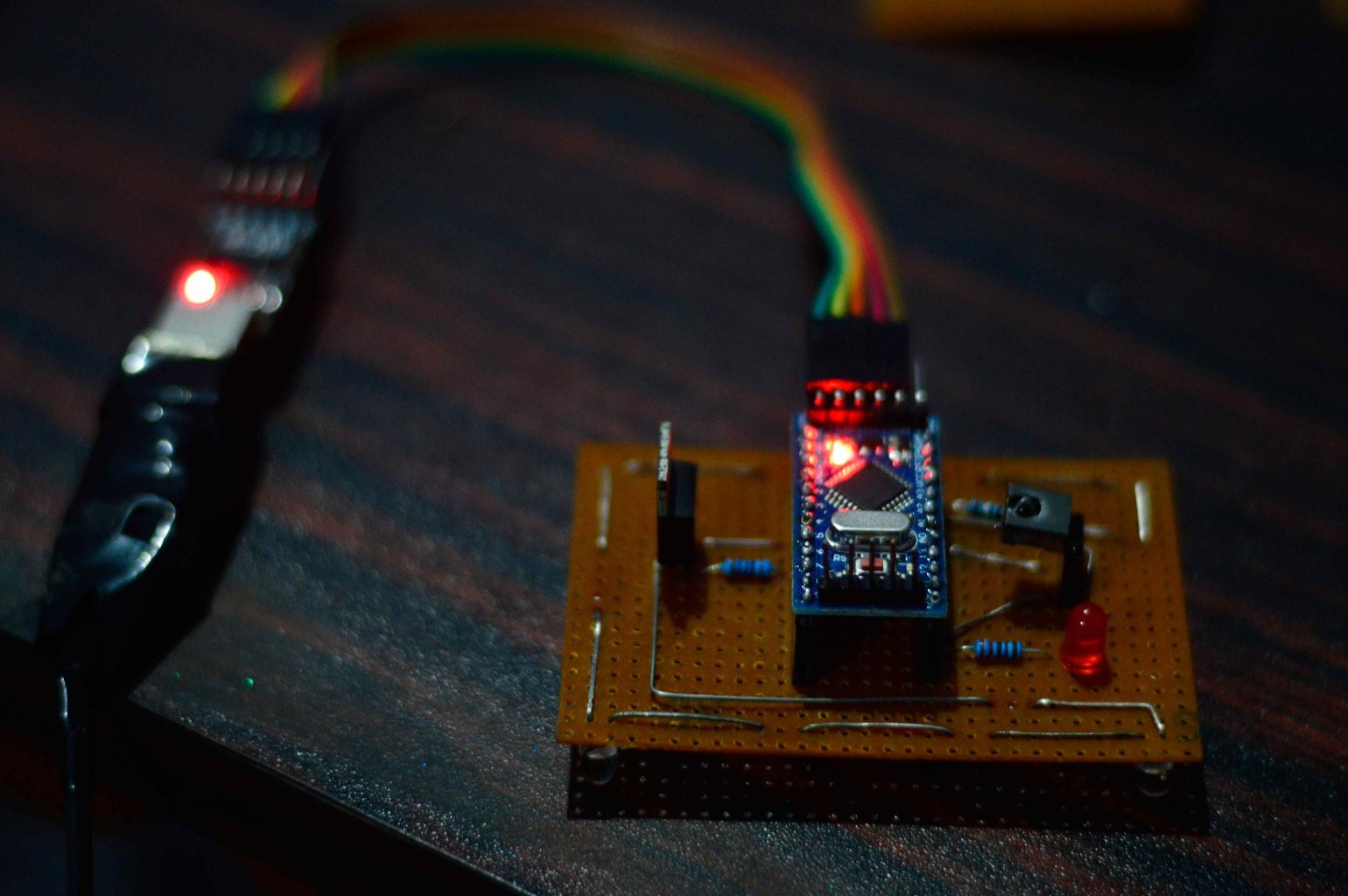
Now the test set-up in place, we can read some remote codes to use in our Arduino code, read codes of all buttons we are using in this project.
I found nice article about Arduino-IRremote library at https://www.pjrc.com/teensy/td_libs_IRremote.html which explains a lot about this library. I developed my code based on ‘example program for receiving’ in that article.
A simple if condition can be written to translate what to do when master remote command is received. Infrared codes can be sent from the same set-up by using IRsend object.
Always keep any camera around when testing this as infrared light can only be seen with IR sensitive cameras
This is second time I am building the same project, in previous one I did not use the library, I literally measured micro seconds gap between the Infrared pulses from remote and made those delay numbers as a byte array and blinked IR led with those gaps in between. Major problem with that kind of set-up is memory, Arduino mini pro has very little memory and those byte arrays are huge. And that set-up is also not reliable as using library.
Attachments

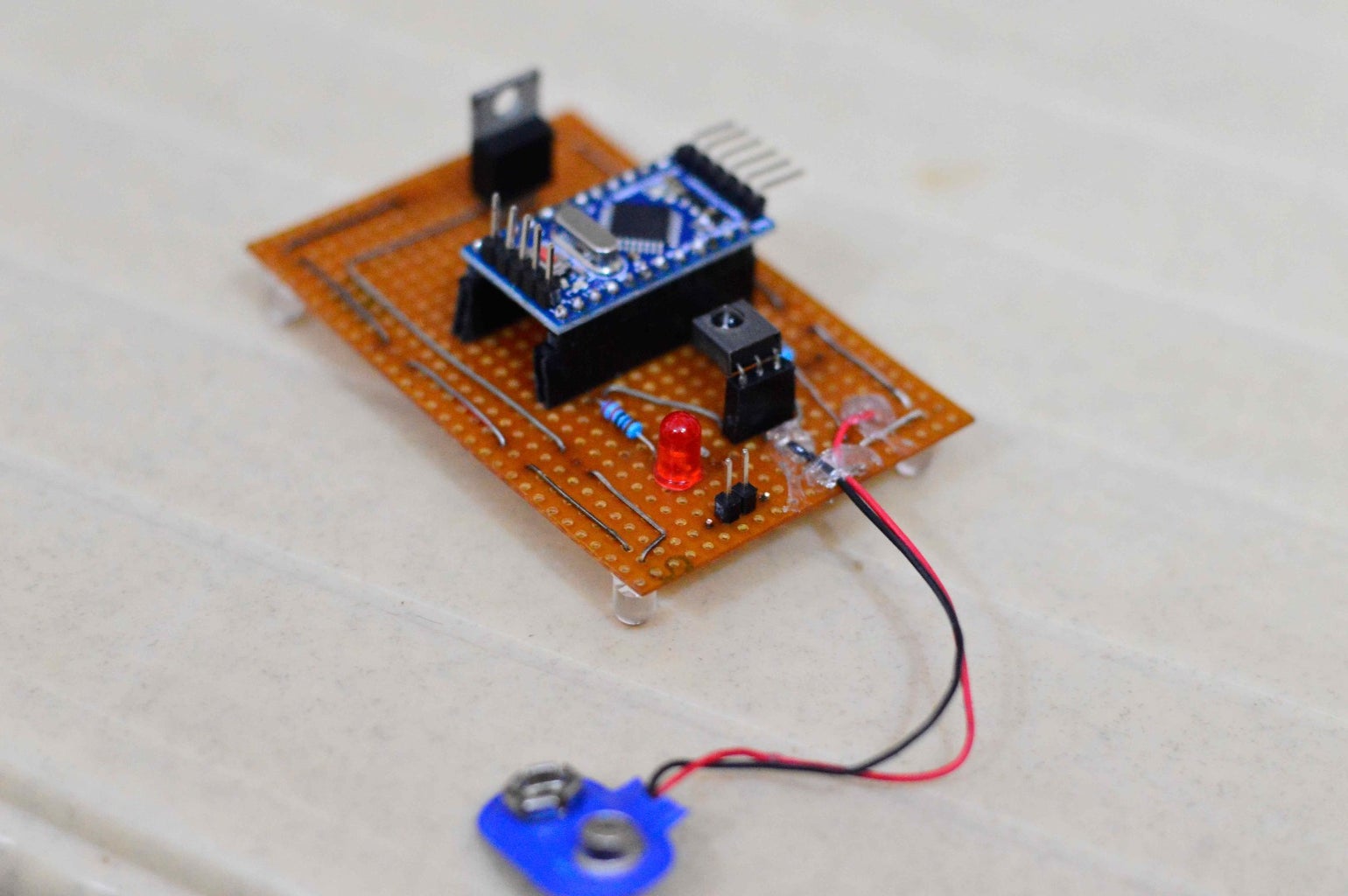
Step 4: Building


So after testing the code it is time to move whole test set-up to permanent board. I have used FQP50N06 N-channel MOSFET to amplify the PWM signal from Arduino pin 3.
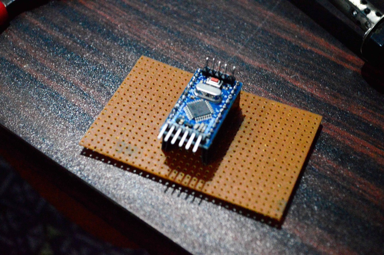
I used female header to mount Arduino to the perfboard so that I can remove the Arduino if anything goes bad in future.
I don’t trust sensor because this is second time I am building this project, so I am re using same sensor for 3 times. So I am using female headers to mount the sensor, so that it can be replaced any time. It can also be helpful to extend the sensor in case I need any adjustments.
Digital pins of Arduino can only handle 40mA and I don’t have any transistor that can handle 500 mA current draw for group of LED’s, so I decided to use an N-channel MOSFET to amplify the PWM signal from Arduino pin 3.
If the LED’s are below 40mA they can be directly connected to digital pin of Arduino by adding 220ohms resistor.
I designed the layout in fritzing and followed the schematics to solder on to a perfboard.
For portability purpose I am planning to use 9v battery to power the device by connecting to raw pin of Arduino but I am concerned that those high power LED's can drain battery quickly. So first I will use this device with battery and mark the battery life if it is reasonable I will continue to use on battery otherwise I will switch to a wall adapter of around 9 volts. So I also have added two male jumper pins to board to connect positive and negative wires form power supply.
I also added a red led with 220ohm resistor to indicate the activity of arduino, next key press can be accepted after led is off.
This project can be rebuilt for any setup by simply modifying codes and if condition in the Arduino code.
Now I should find good enclosure to fit everything nicely.
#include <IRremote.h>

const int RECV_PIN = 12;
const int ACT_PIN = 11;
int repeat = 3;

unsigned long currcode;
unsigned long prevcode;

//settop box codes
const unsigned long stpower = 0x11D9D02F;
const unsigned long volumeup1 = 0x11D948B7;
const unsigned long volumedown1 = 0x11D958A7;
const unsigned long volumeup2 = 0x11D98E71;
const unsigned long volumedown2 = 0x11D94EB1;

//tv codes
unsigned long tpower = 0x1CE338C7;
unsigned long av = 0x1CE328D7;

//soundbar codes
unsigned long sbpower = 0x1100C;
unsigned long aux = 0x11038;
unsigned long volumeup = 0x11010;
unsigned long volumedown = 0x11011;

IRrecv irrecv(RECV_PIN);
IRsend irsend;
decode_results results;

void setup()
{
  Serial.begin(9600);
  irrecv.enableIRIn();
  pinMode(ACT_PIN, OUTPUT);
  irrecv.blink13(true);
}void loop() {
  if (irrecv.decode(&results)) {
    if (results.decode_type != UNKNOWN )
    {
      if (results.value != REPEAT )
      {
        currcode = results.value;
      }
      else if (results.value == REPEAT )
      {
        if (prevcode == volumeup1 || prevcode == volumeup2 || prevcode == volumedown1 || prevcode == volumedown2)
        {
          currcode = prevcode;
        }
        else
        {
          currcode = 0;
        }
      }
      if (currcode == stpower)
      {
        digitalWrite(ACT_PIN, HIGH);
        Serial.println("power");
        irsend.sendNEC(tpower, 32);
        delay(500);
        irsend.sendRC6(sbpower, 20);
        delay(1500);
        irsend.sendNEC(av, 32);
        delay(500);
        digitalWrite(ACT_PIN, LOW);
      }
      else if (currcode == volumeup1 || currcode == volumeup2)
      {
        for (int i = 0; i < repeat; i++)
        {
          digitalWrite(ACT_PIN, HIGH);
          Serial.println("volumeup1");
          irsend.sendRC6(volumeup, 20);
          delay(500);
          digitalWrite(ACT_PIN, LOW);
        }
      }
      else if (currcode == volumedown1 || currcode == volumedown2)
      {
        for (int i = 0; i < repeat; i++)
        {
          digitalWrite(ACT_PIN, HIGH);
          Serial.println("volumedown1");
          irsend.sendRC6(volumedown, 20);
          delay(500);
          digitalWrite(ACT_PIN, LOW);
        }
      }
      else
      {
        //do nothing
      }
    }
    prevcode = currcode;
    irrecv.resume();
    irrecv.enableIRIn(); //trust me this has to be done again
  }
}Step 5: Transmitting Pin
Transmit pin for this library is dependent on the Arduino model we are using, for example if we are using Arduino mega the transmit pin is digital pin 9, if we are using mini pro or uno transmit pin is digital pin 3. That transmit pin is based on timer of the AVR chip we are using which is different for different chips.
For more details open IRremoteInt.h file in libraries\Arduino-IRremote-master folder
There we can find some code which determines which timer to use when using different boards for the library.
If you really want, you can modify this code to change PWM pin for transmitting.
// Define which timer to use
//
// Uncomment the timer you wish to use on your board.
// If you are using another library which uses timer2, you have options to
//   switch IRremote to use a different timer.
// Arduino Mega

#if defined(__AVR_ATmega1280__) || defined(__AVR_ATmega2560__)
	//#define IR_USE_TIMER1   // tx = pin 11
	#define IR_USE_TIMER2     // tx = pin 9
	//#define IR_USE_TIMER3   // tx = pin 5
	//#define IR_USE_TIMER4   // tx = pin 6
	//#define IR_USE_TIMER5   // tx = pin 46

// Teensy 1.0
#elif defined(__AVR_AT90USB162__)
	#define IR_USE_TIMER1     // tx = pin 17

// Teensy 2.0
#elif defined(__AVR_ATmega32U4__)
	//#define IR_USE_TIMER1   // tx = pin 14
	//#define IR_USE_TIMER3   // tx = pin 9
	#define IR_USE_TIMER4_HS  // tx = pin 10

// Teensy 3.0 / Teensy 3.1
#elif defined(__MK20DX128__) || defined(__MK20DX256__)
	#define IR_USE_TIMER_CMT  // tx = pin 5

// Teensy-LC
#elif defined(__MKL26Z64__)
  #define IR_USE_TIMER_TPM1 // tx = pin 16

// Teensy++ 1.0 & 2.0
#elif defined(__AVR_AT90USB646__) || defined(__AVR_AT90USB1286__)
	//#define IR_USE_TIMER1   // tx = pin 25
	#define IR_USE_TIMER2     // tx = pin 1
	//#define IR_USE_TIMER3   // tx = pin 16

// Sanguino
#elif defined(__AVR_ATmega644P__) || defined(__AVR_ATmega644__)
	//#define IR_USE_TIMER1   // tx = pin 13
	#define IR_USE_TIMER2     // tx = pin 14

// Atmega8
#elif defined(__AVR_ATmega8P__) || defined(__AVR_ATmega8__)
	#define IR_USE_TIMER1     // tx = pin 9

// ATtiny84
#elif defined(__AVR_ATtiny84__)
  #define IR_USE_TIMER1     // tx = pin 6

//ATtiny85
#elif defined(__AVR_ATtiny85__)
  #define IR_USE_TIMER_TINY0   // tx = pin 1

// Arduino Duemilanove, Diecimila, LilyPad, Mini, Fio, Nano, etc
#else
	//#define IR_USE_TIMER1   // tx = pin 9
	#define IR_USE_TIMER2     // tx = pin 3

#endif

Participated in the
Full Spectrum Laser Contest 2016

Participated in the
Arduino All The Things! Contest


